The problem
The previous method of evaluating non-uniformity was a very well calibrated photovoltaic cell that would sweep under the light source, measure the intensity at individual grid points and output a graph. This was accurate but slow – at least a couple minutes per test. Between each sweep you would make tiny adjustments to the light source that had unintuitive effects on the output. This was very frustrating and led to almost superstitious adjustment technique: “sometimes if you start at the right side and sweep slowly towards the middle, you’ll get better uniformity, but only if you have ‘the touch'”, etc.
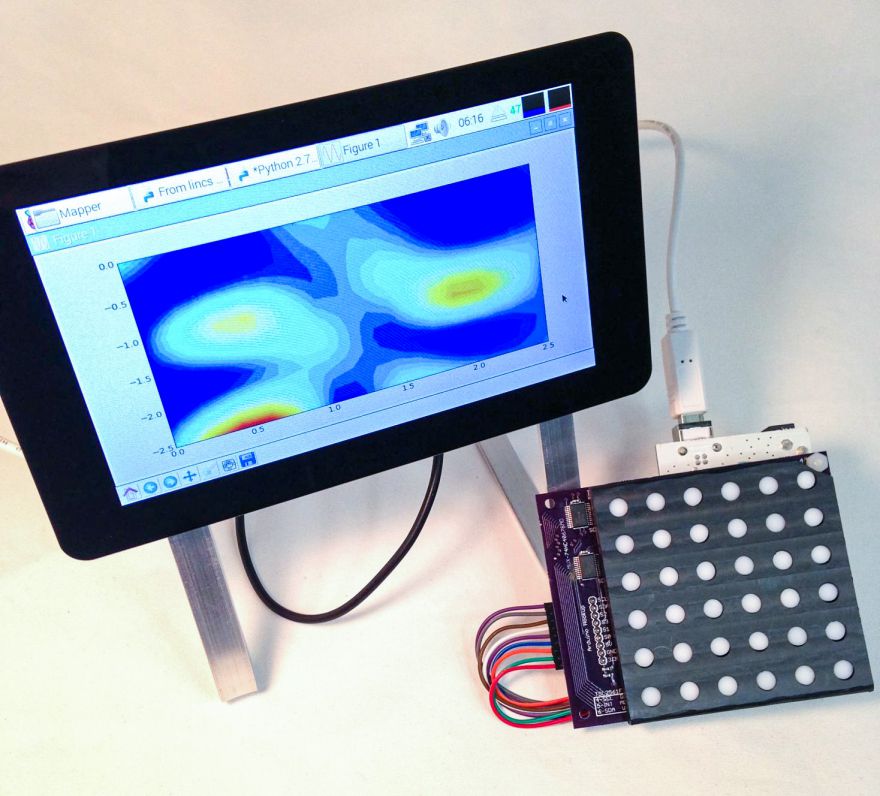
This non-uniformity mapper was designed to make that process easier. It would close the feedback loop of measurement and adjustment and allow for continuous sampling of the light profile.
Goal – Make a test fixture that instantly measures the spatial non-uniformity of a light source.
Sensor selection
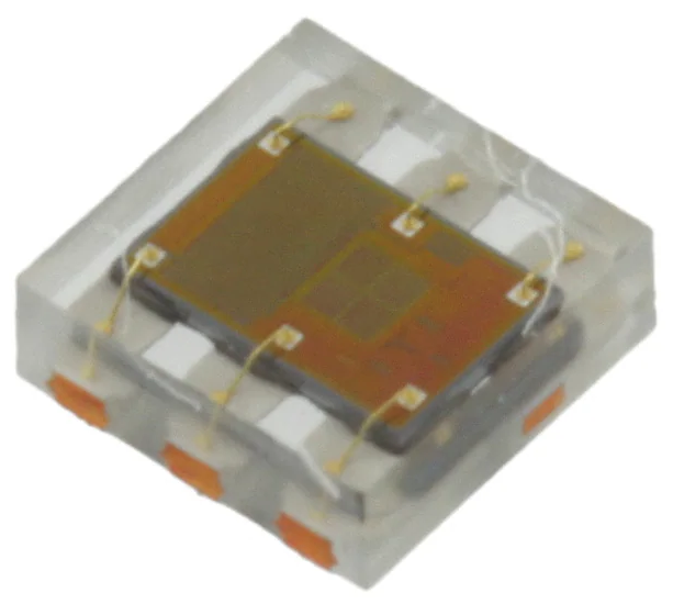
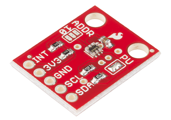
For simplicity, I wanted something that could convert illuminance to a digital signal. I started with a few of the breakout boards shown above from Sparkfun and this tutorial (Let There Be Light!) as a proof of concept. Starting with this breakout board also allowed me to use the Arduino library written for this sensor which was a huge help. The sensor itself was the TSL2561 (a light-to-digital converter).
The initial results were decent and were immediately helpful with some troubleshooting. This initial testing also allowed me to test whether addressing multiple sensors through an Arduino would work. It didn’t work so I had to multiplex all the signals using a separate MUX chip which I was able to quickly incorporate into the test setup.
PCB
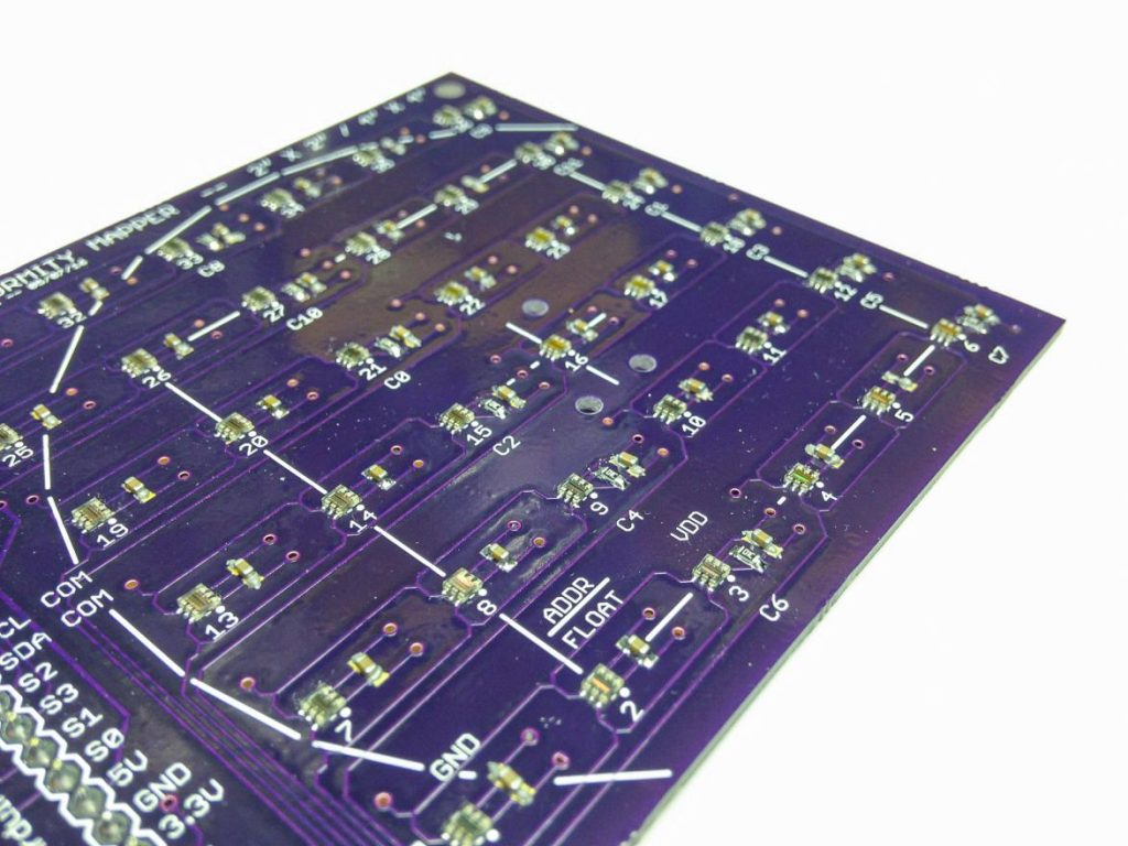
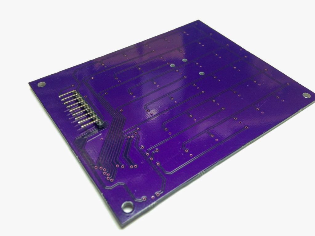
The lights sensors on the PCB were placed in the same locations as on the official, slow test. The circuitry was pretty simple, but this was my first PCB design so learning the software took a while.
I got 3 boards (minimum quantity) from OSH Park for $60 and other components including sensors, solder paste etc. for less than $100.
Diffusers
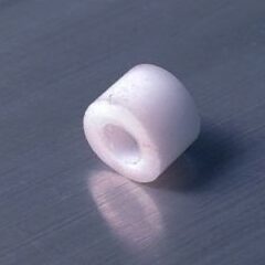
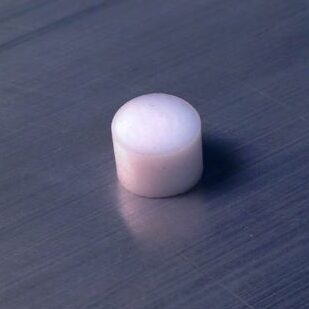
The diffusers were little caps made from a Teflon rod that was cut to size and drilled out. These cut down the light to a manageable intensity which didn’t oversaturate the sensors and (theoretically) prevented directional bias from incoming light rays (almost all the light was coming straight down from the top). In practice I found the height of the diffuser and sharp edges probably led to complex internal reflections that made it difficult to calibrate the sensors.
Diffusor isolator


In an attempt to eliminate any cross-talk from the diffusers which may have been leading to calibration issues, I made an isolator that would drop over all the Teflon dots. It didn’t completely eliminate the issue but it was fun to make and I liked the fit of it so I left it on. It probably wouldn’t make it to a final design without more conclusive testing to justify it.
Display

The display was the easiest part to get working, just a touchscreen monitor and a Raspberry Pi 3 so everything was plug-and-play. Together they cost under $100 – pretty crazy for a fully functional computing setup. I liked the portability and simplicity of the touchscreen but a wireless keyboard and mouse could be used as well.
Assembly
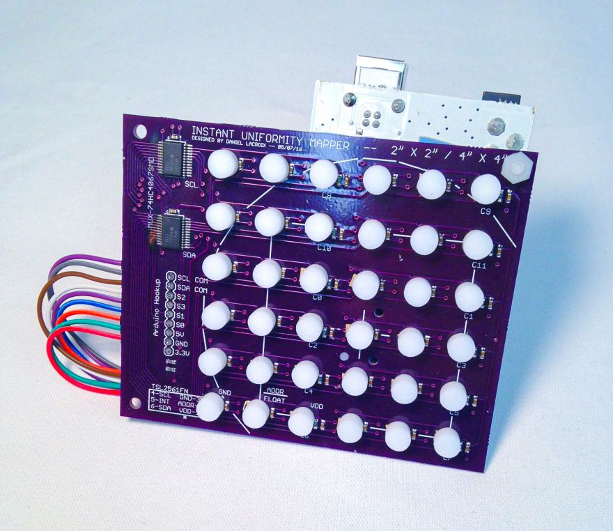
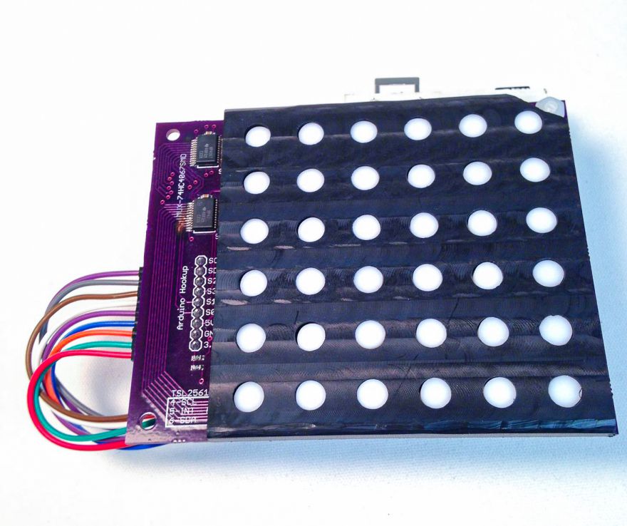
I’m pretty happy with the appearance and functionality although I would reroute the wires for future builds so they don’t stick out the side.
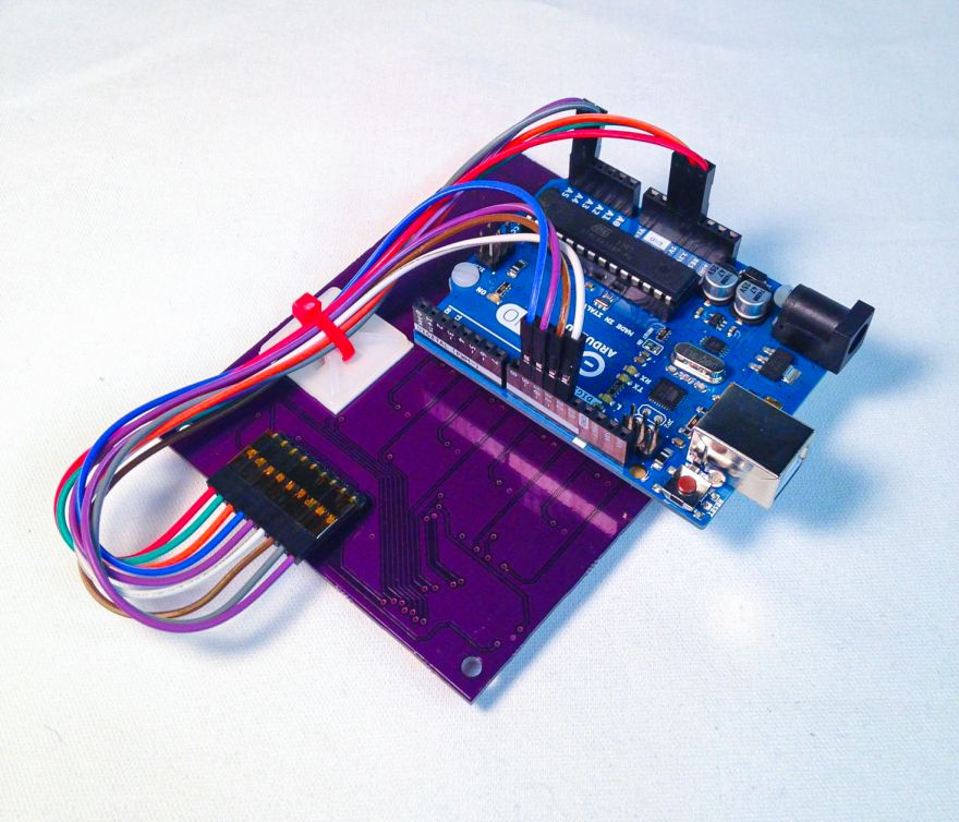
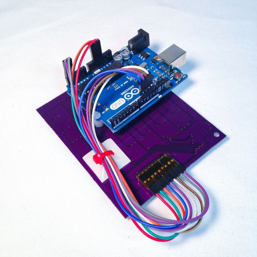
The Arduino mounts right to the PCB which makes it pretty compact and portable.
Interface & display
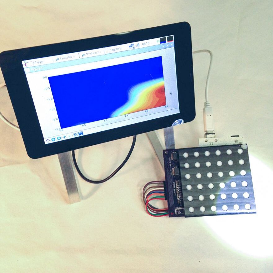
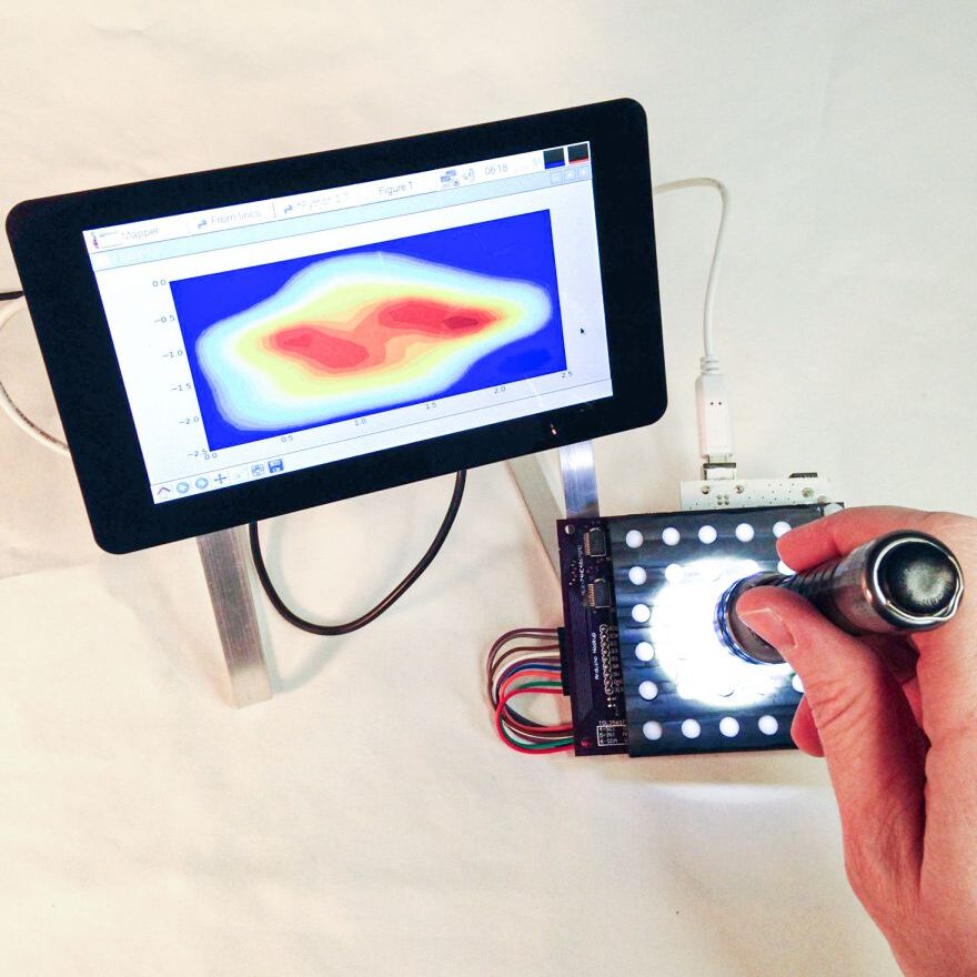
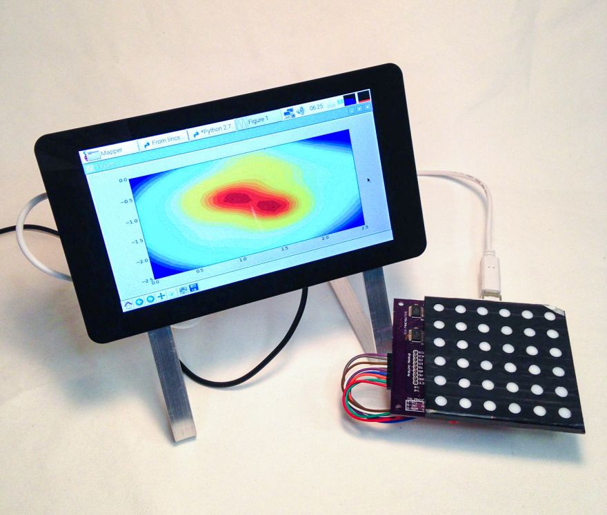
In this setup there’s a Raspberry Pi doing the display and talking to the Arduino that’s talking to the sensors. You could probably get rid of the Arduino and do everything from the Pi but the current setup helped me troubleshoot things in blocks and I just needed something functional. The plotting was harder than expected to get running smoothly. I’m sure there are other display packages that would have handled it better. I also could have simplified the plot and made a grid of colored squares that mapped to the sensors but I felt the contour plot more accurately represented the shape of the beam profile. If I were to redo the code for the visualization I would probably explore Processing or search harder for a package/language that would be better suited for this type of real-time output.
Going forward
While useful, the sensor calibration issues and inconsistencies in this device kept it from being as useful as I hoped it would be. I think it could have benefited from a second generation attempt but I had to move on to other projects. It was, however, a great chance to learn about designing these types of projects and where the stumbling blocks are.
Please tell me more about this. May I ask you a question?
Sure! What do you want to know?
Thank you for your help and this post. It’s been great.