– (and kinematic coupling) –
Harmonic drives (or strain wave gearing/harmonic gearing – Wikipedia) use a flexible inner gear driven by an ellipse that meshes with a rigid outer gear. They’re less frequently used than standard mechanisms like planetary gears but have found a solid niche in precision, high-torque and space applications.
Some of their attractive properties:
- No backlash
- Great repeatability
- High gear ratio (mine is 39:1, but they can go as high as 320:1)
- High torque (tooth profile info from HarmonicDrive company)
- Low wear
As you might have guessed, they’re also pretty expensive.
This video gives a good overview of how they work.
Why they’re good
Seems a little weird, right? How can something flexible be stronger and more precise than something rigid? Even technically minded people often assume that anything thin enough to be flexible can’t be strong. But how an object is loaded determines everything about its performance. You can easily squeeze the top edges of a plastic cup together but can’t twist it along it’s axis since tubes and cups have great torsional strength.
So, the benefits of harmonic drives aren’t due to crazy manufacturing tolerances or super-alloys, they’re all due to the geometry. Because the flex spline cup is nearly the same shape as the rigid outer spline, it means most of the teeth are fully or partially engaged and you can get really high tooth engagement percentages which makes it strong and precise. Instead of just one or a few teeth being in contact like in a normal gear, you can get up to 30% tooth engagement around the whole ring.
So, you can deform the spline cup in one direction to get more of the features you want, like high tooth engagement (high torque and no backlash/high precision) while not sacrificing anything because your deformable spline cup also happens to be strong in torsion.
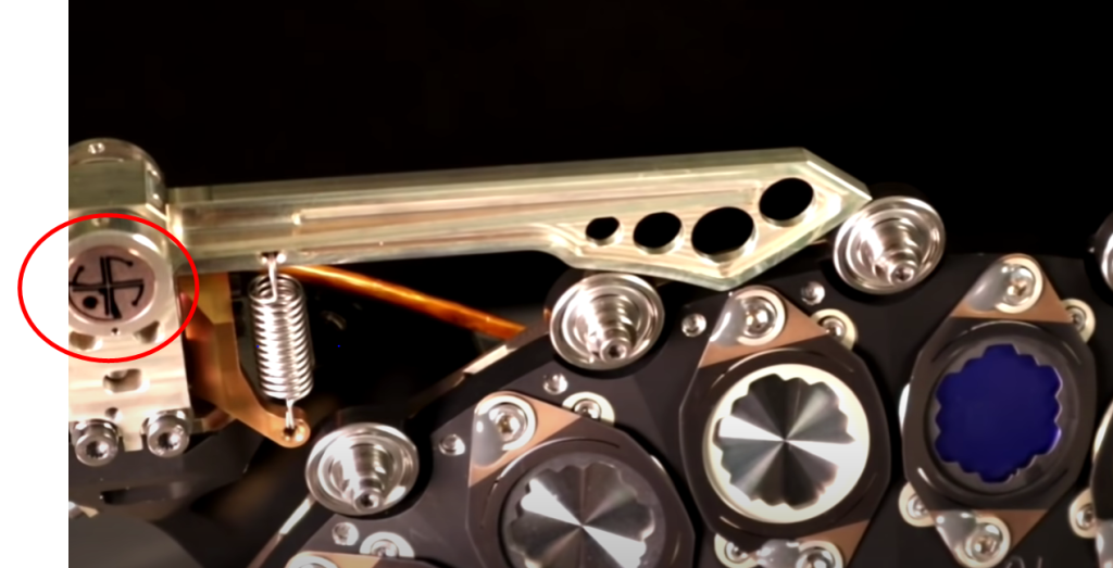
Applications
Harmonic drives are frequently used in space applications, for example the Hubble Telescope and the Mars Pathfinder rover. One of the first major applications was in the Lunar Roving Vehicle (Wikipedia)(Google Images) where it was used as a reduction mechanism between the wheels and the DC motors which were spinning at 10,000 rpm! They’re also used in industrial robot joints due to their high performance and compactness. I suspect they’d be used everywhere if they weren’t so expensive.
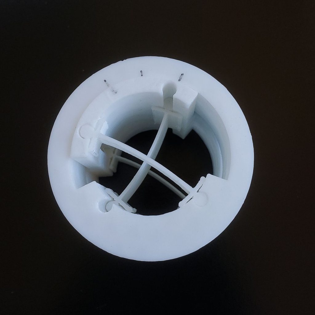
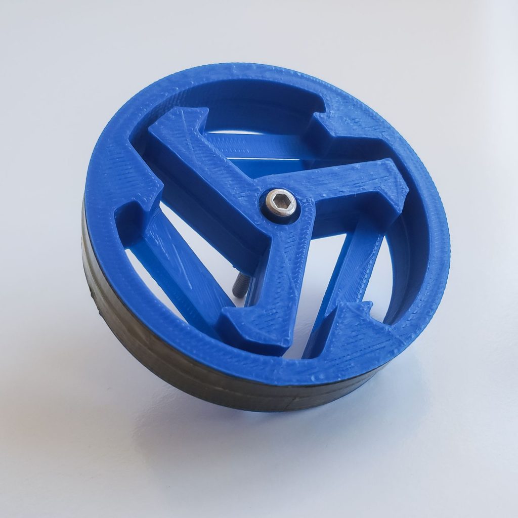
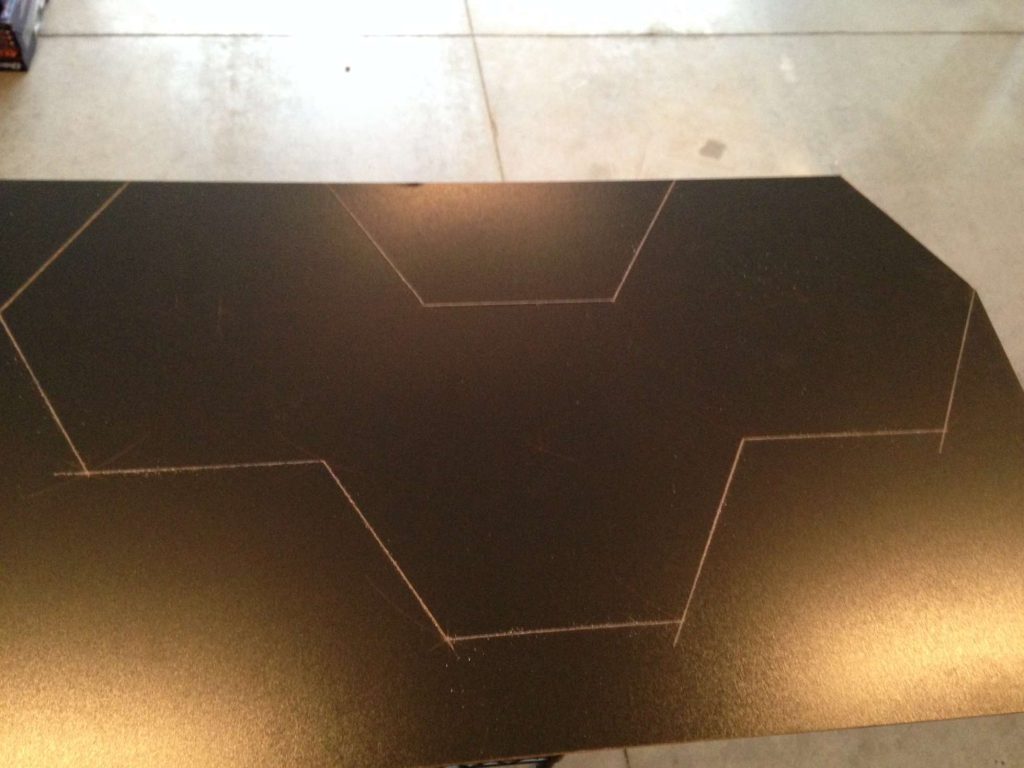
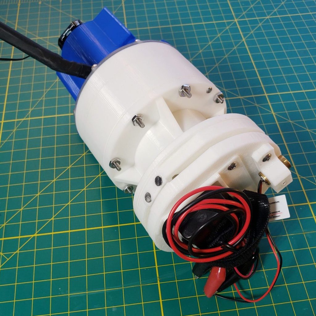
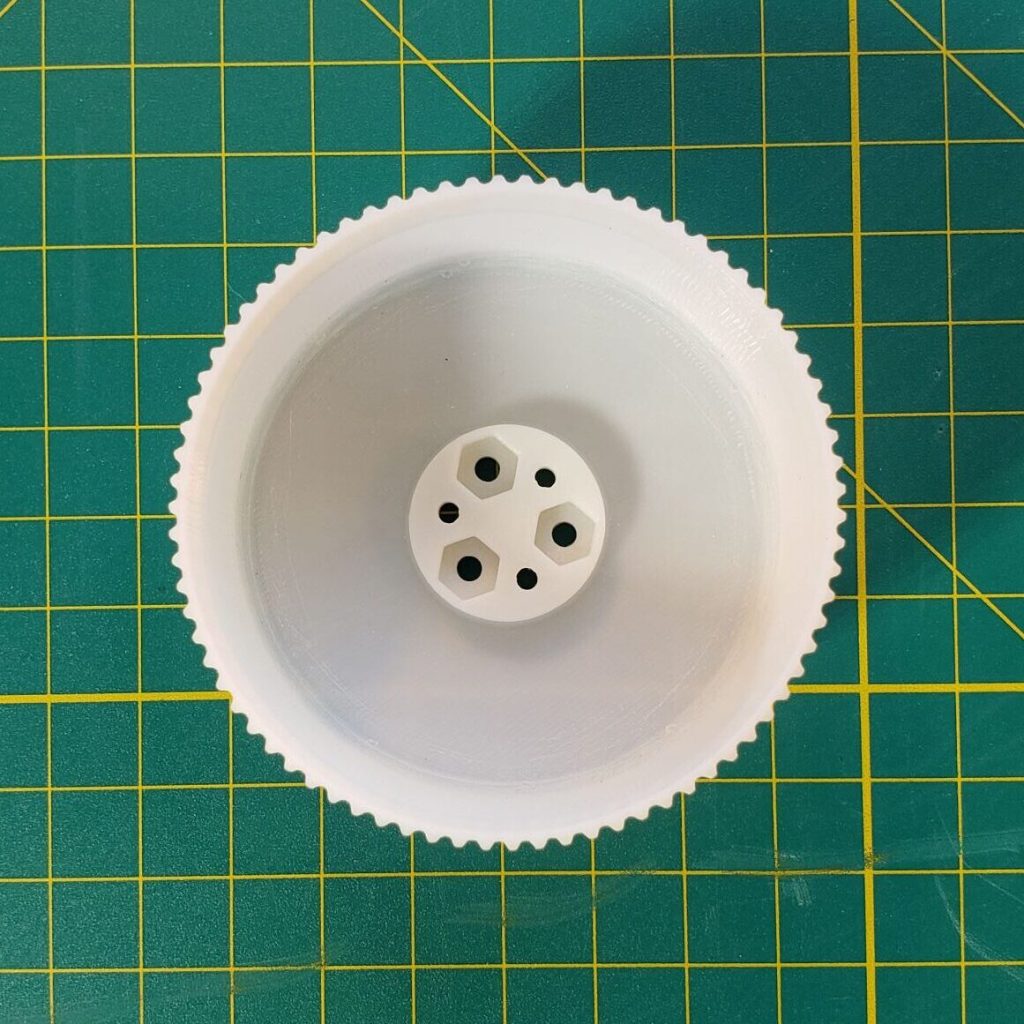
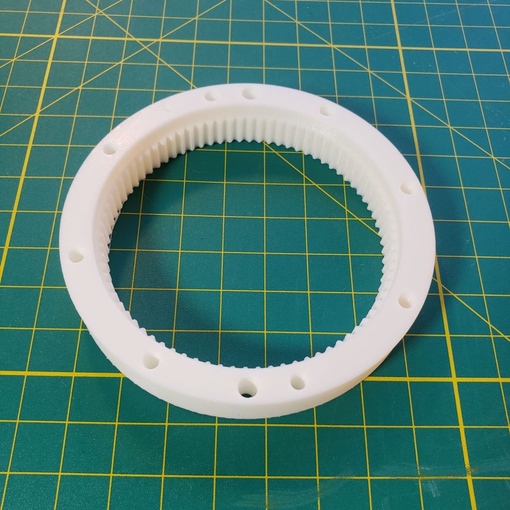
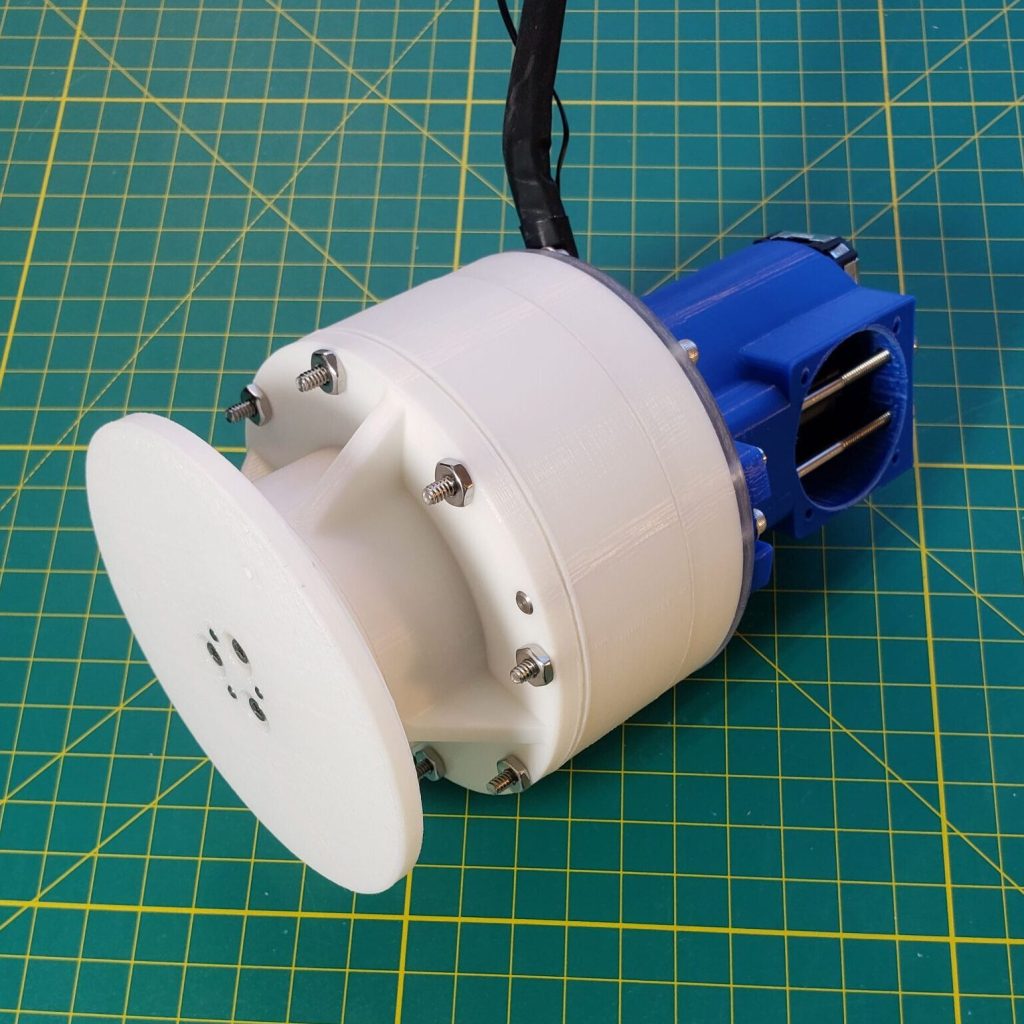
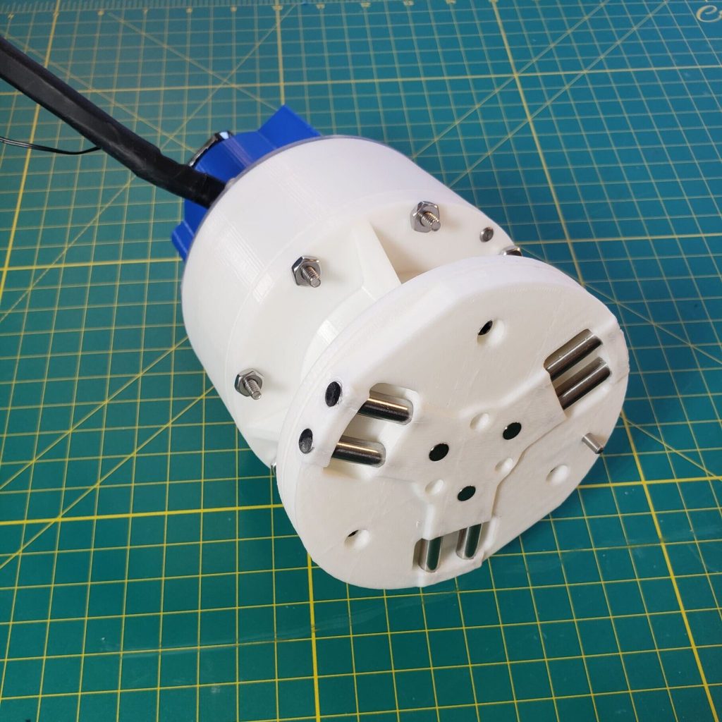
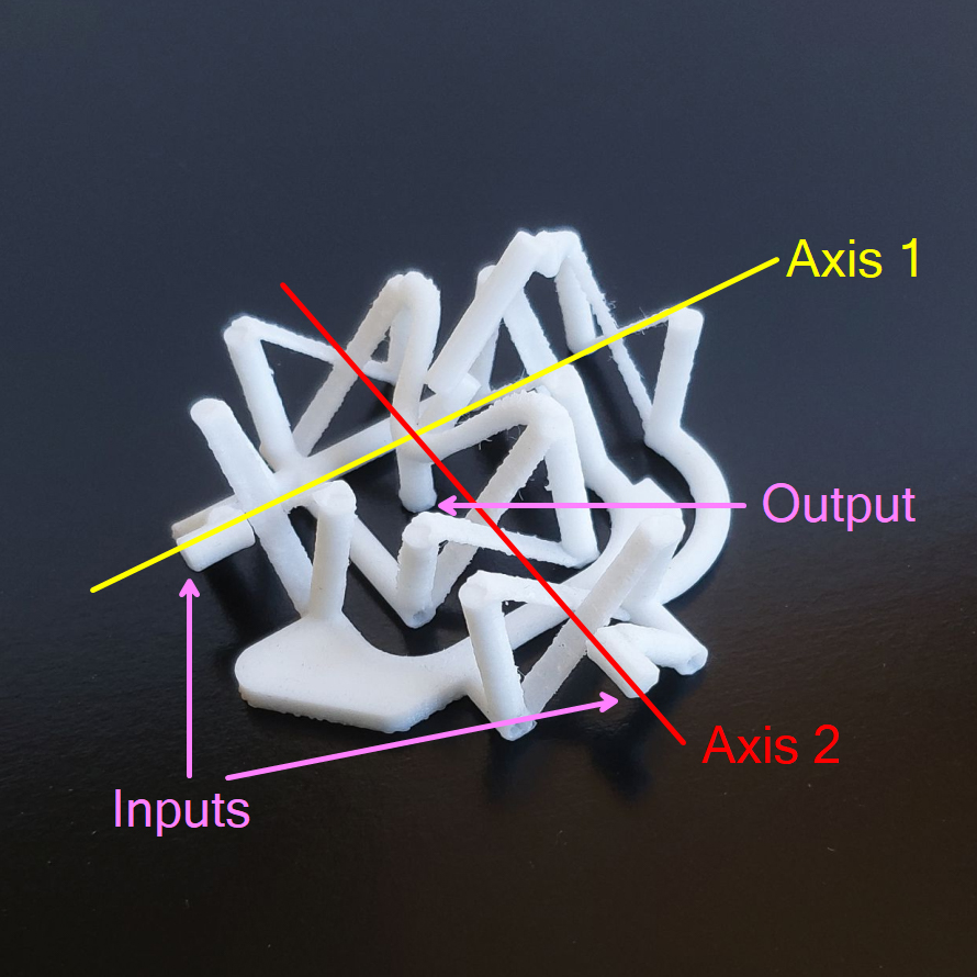
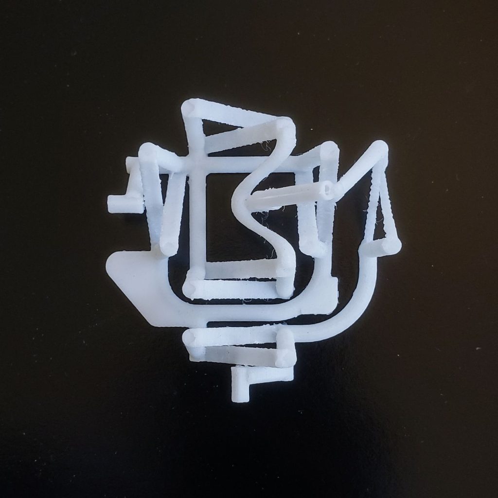
3D printed design
Harmonic drive – My design geometry is basically just a series of educated guesses. I did find some other models online but they weren’t editable and didn’t have alignment features like dowel pins or removeable parts like the outer spline. I also found some old technical papers about harmonic gearing tooth geometry. I originally tried to model optimal tooth geometry based on my tooth count, spline diameter etc., sort of like you’d do with an involute gear but couldn’t find a simple geometric or mathematical way to solve it given the flexing of the inner spline. I could have simulated it in software but at that point it would have just been for the sake of simulating it. My printer isn’t super precise, there’s a large amount of elastic averaging going on anyway and I wasn’t sure that it would work at all, so better to test first, optimize later. It ended up being more performant than I was anticipating without the optimization, so mark one down for educated guesses.
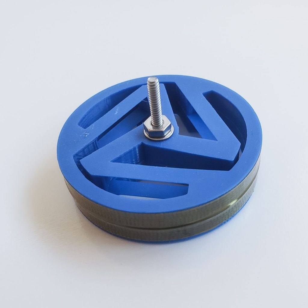
The splines clearance did take a few iterations to get right. Do to under/over extrusion of my printer, the first tests didn’t fit well. Changing things like the diameter by .010″ had huge effects on the feel of the gear contact. Most of the backlash seems to come down to this clearance but if you make it too small you end up just mashing the teeth together and destroying them.

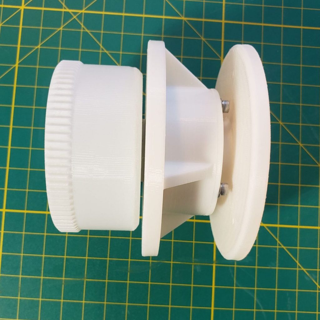
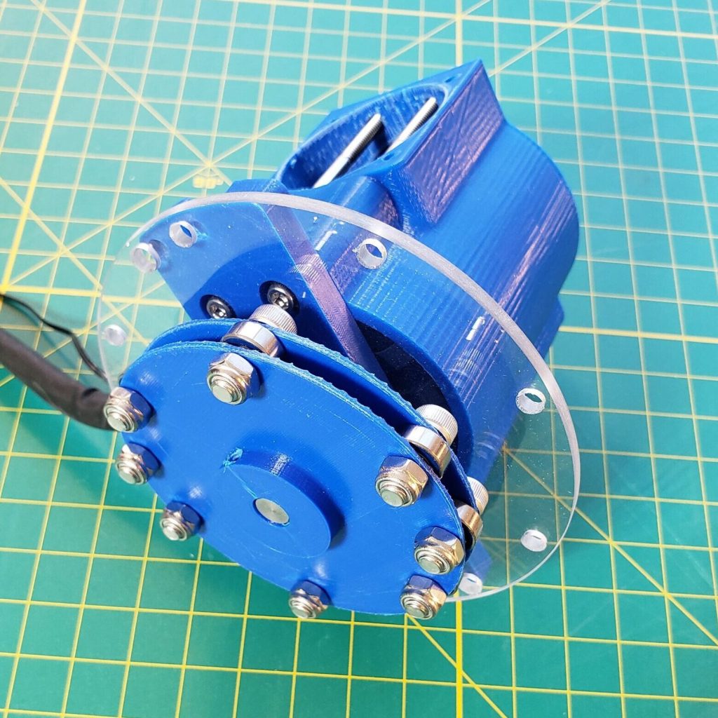
Why I like 3D printing – I’ve seen a lot of 3D print designs that aim to be all ,or mostly, printed which I don’t see the appeal of. If it was cheap and easy enough I’d make this whole thing out of machined metal, but since that’s not cheap or easy, I figure, why not use as many low-cost precision components, like dowels, bearings and hardware as possible? Then I can make the complicated parts out of printed plastic while not sacrificing too much. I’ve been really happy with this approach and am always on the lookout for ways to sneak more performance into my designs, whether it’s with hardware or the designs of the 3D prints themselves. “Tony Stark was able to build this in a cave – with a box of scraps!” is constantly in the back of my mind.
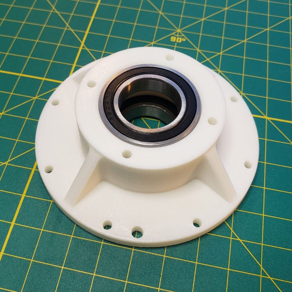
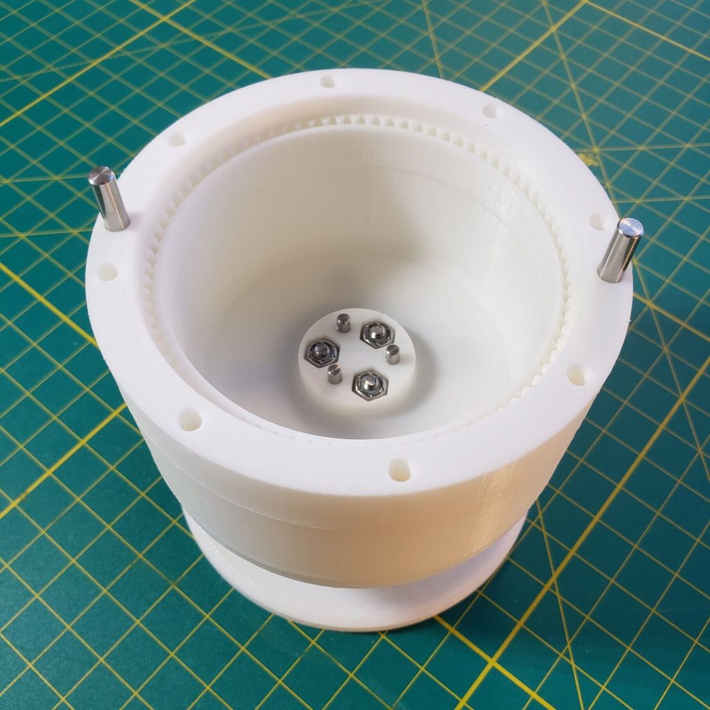
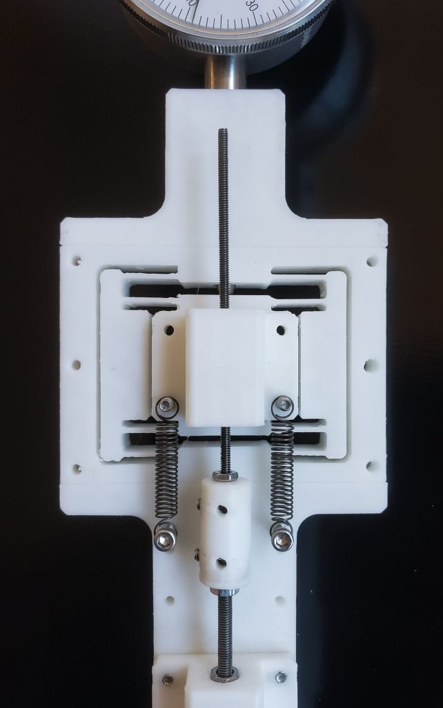
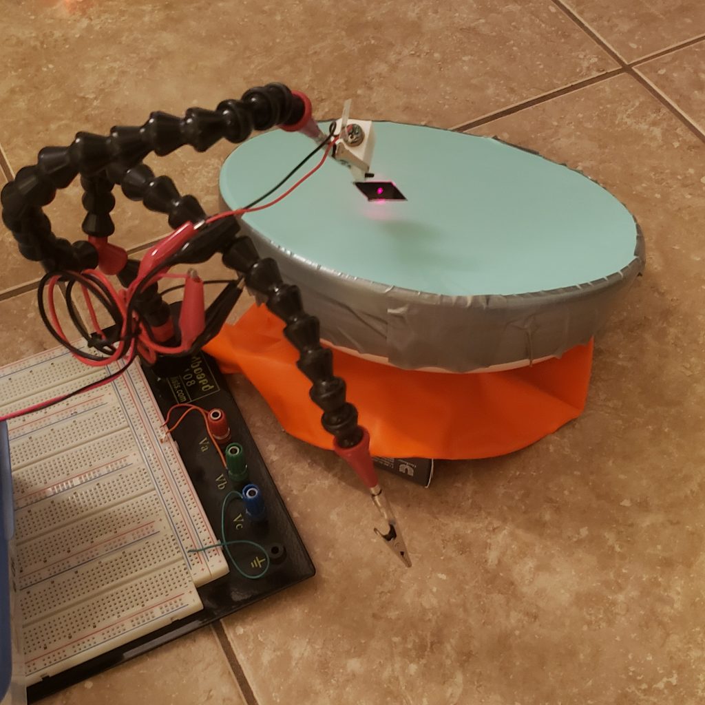
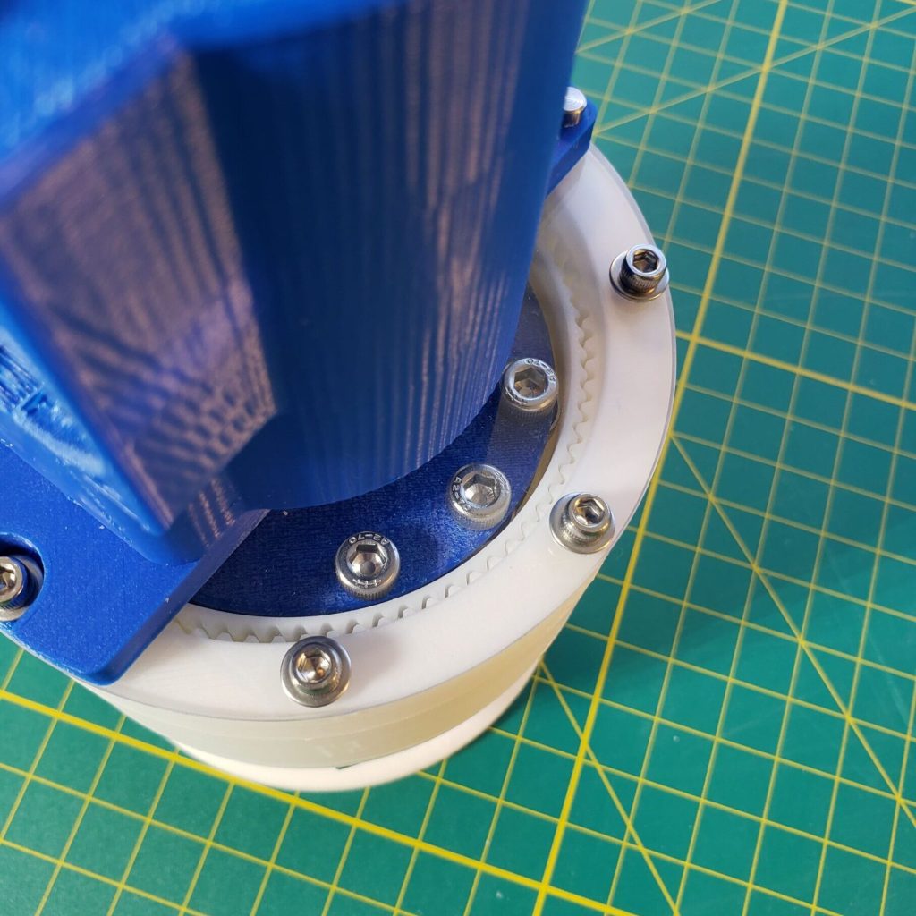
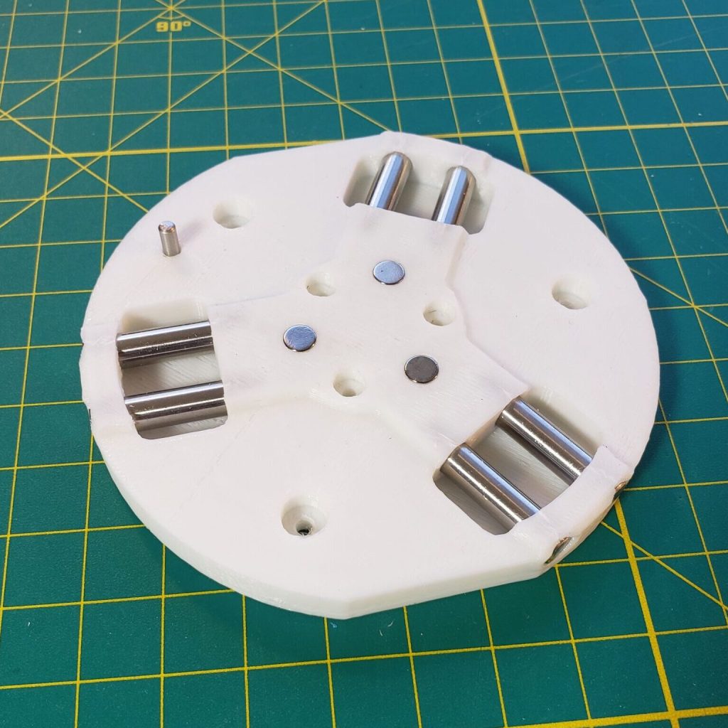
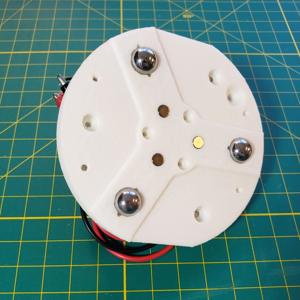
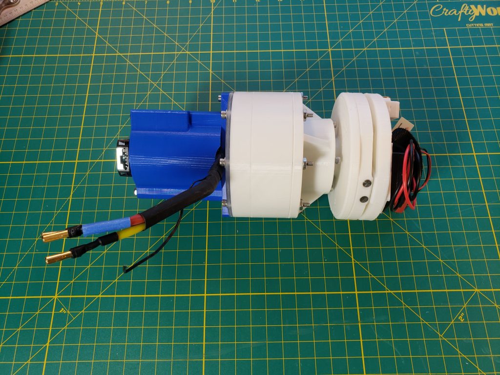
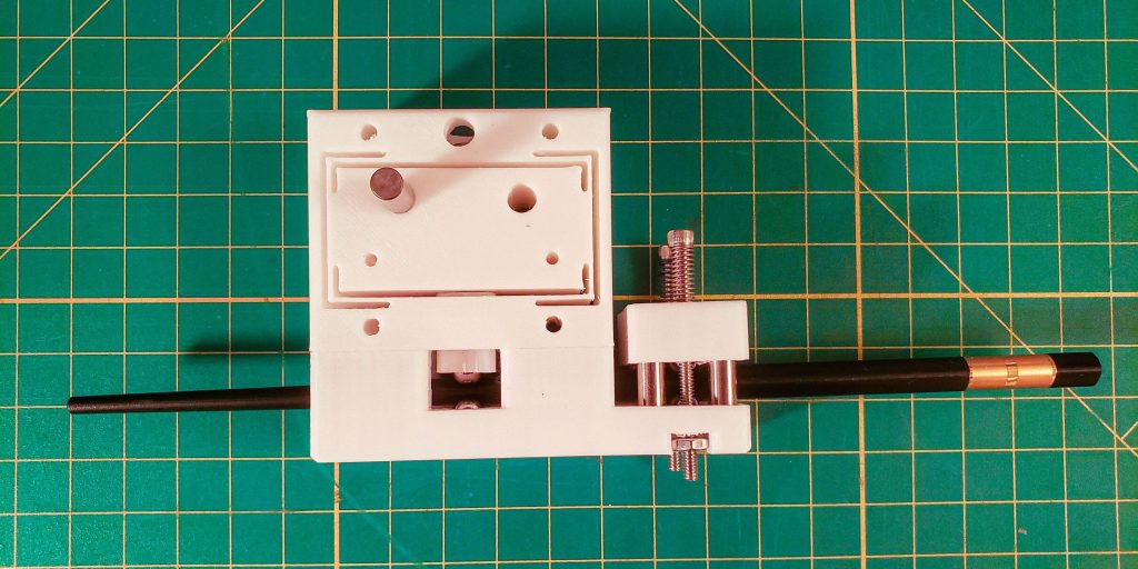
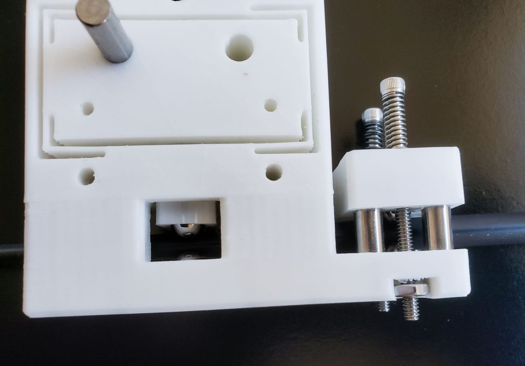
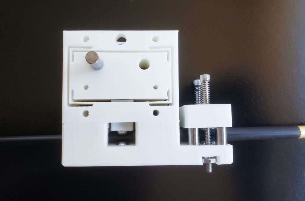
Kinematic coupling – I also attached a kinematic coupling (Wikipedia)(a repeatable and self-aligning fixture) which I had made previously to see what the combined precision of the harmonic drive and kinematic coupling would be. It also provided a standardized interface where I could just print a new ball bearing mount with a different payload/instrument on it and swap them out with no disassembly.
Motor input – The motor is a simple off-the-shelf BLDC (brushless DC) motor driven by an ODrive which is an open source BLDC driver. I want to do more with these ODrives in the future. They’re pretty handy for prototyping although the programming interface is a little cumbersome. With a better UI they could be an industrial “LEGO” type tool.
Specs
- Tooth count: flex spline (78), outer spline (80)
- Gear ratio: 78 / (80 – 78) = 39:1
- flex spline teeth / (outer spline teeth – flex spline teeth)
- The flex and outer splines typically differ by 2 teeth
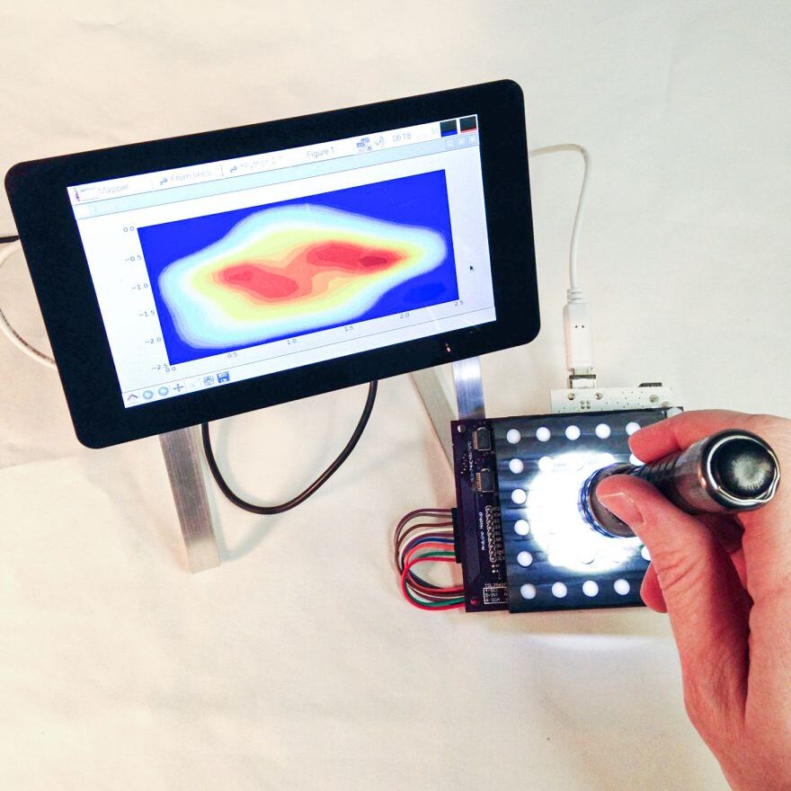
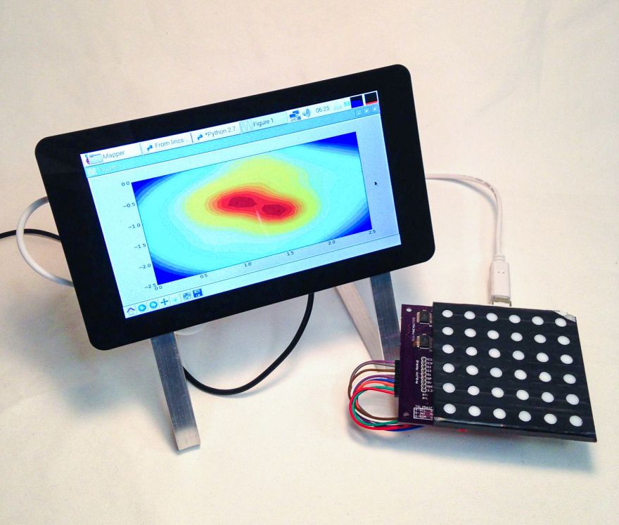
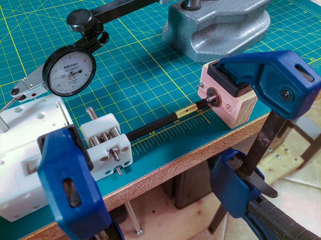
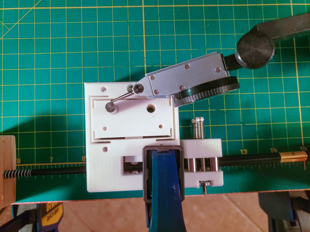
- Repeatability: < .015 deg [0.89 arc-min]
- Back of envelope:
- Laser visual position resolution: < 1/32″ = 0.031″
- Laser distance: 10′-12′
- No detectable movement of laser position greater than laser visual position resolution
- Repeatability = arctan(.031″ / 120″) = < .015 deg [0.89 arc-min]
- Back of envelope:
Full assembly and videos
![\[ \frac{1}{TPI_{eff}} = \frac{1}{TPI_1} - \frac{1}{TPI_2} = P_{eff} \]](https://danlacroix.a2hosted.com/wp-content/ql-cache/quicklatex.com-4d13a57503cb718cc68ec49e748feebf_l3.png "Rendered by QuickLaTeX.com")