Harmonic drive 3D print

– (and kinematic coupling) –
Harmonic drives (or strain wave gearing/harmonic gearing – Wikipedia) use a flexible inner gear driven by an ellipse that meshes with a rigid outer gear. They’re less frequently used than standard mechanisms like planetary gears but have found a solid niche in precision, high-torque and space applications.

Some of their attractive properties:

As you might have guessed, they’re also pretty expensive.
This video gives a good overview of how they work.

Why they’re good

Seems a little weird, right? How can something flexible be stronger and more precise than something rigid? Even technically minded people often assume that anything thin enough to be flexible can’t be strong. But how an object is loaded determines everything about its performance. You can easily squeeze the top edges of a plastic cup together but can’t twist it along it’s axis since tubes and cups have great torsional strength.

So, the benefits of harmonic drives aren’t due to crazy manufacturing tolerances or super-alloys, they’re all due to the geometry. Because the flex spline cup is nearly the same shape as the rigid outer spline, it means most of the teeth are fully or partially engaged and you can get really high tooth engagement percentages which makes it strong and precise. Instead of just one or a few teeth being in contact like in a normal gear, you can get up to 30% tooth engagement around the whole ring.

So, you can deform the spline cup in one direction to get more of the features you want, like high tooth engagement (high torque and no backlash/high precision) while not sacrificing anything because your deformable spline cup also happens to be strong in torsion.

Applications

Harmonic drives are frequently used in space applications, for example the Hubble Telescope and the Mars Pathfinder rover. One of the first major applications was in the Lunar Roving Vehicle (Wikipedia)(Google Images) where it was used as a reduction mechanism between the wheels and the DC motors which were spinning at 10,000 rpm! They’re also used in industrial robot joints due to their high performance and compactness. I suspect they’d be used everywhere if they weren’t so expensive.

3D printed design

Harmonic drive – My design geometry is basically just a series of educated guesses. I did find some other models online but they weren’t editable and didn’t have alignment features like dowel pins or removeable parts like the outer spline. I also found some old technical papers about harmonic gearing tooth geometry. I originally tried to model optimal tooth geometry based on my tooth count, spline diameter etc., sort of like you’d do with an involute gear but couldn’t find a simple geometric or mathematical way to solve it given the flexing of the inner spline. I could have simulated it in software but at that point it would have just been for the sake of simulating it. My printer isn’t super precise, there’s a large amount of elastic averaging going on anyway and I wasn’t sure that it would work at all, so better to test first, optimize later. It ended up being more performant than I was anticipating without the optimization, so mark one down for educated guesses.

The splines clearance did take a few iterations to get right. Do to under/over extrusion of my printer, the first tests didn’t fit well. Changing things like the diameter by .010″ had huge effects on the feel of the gear contact. Most of the backlash seems to come down to this clearance but if you make it too small you end up just mashing the teeth together and destroying them.

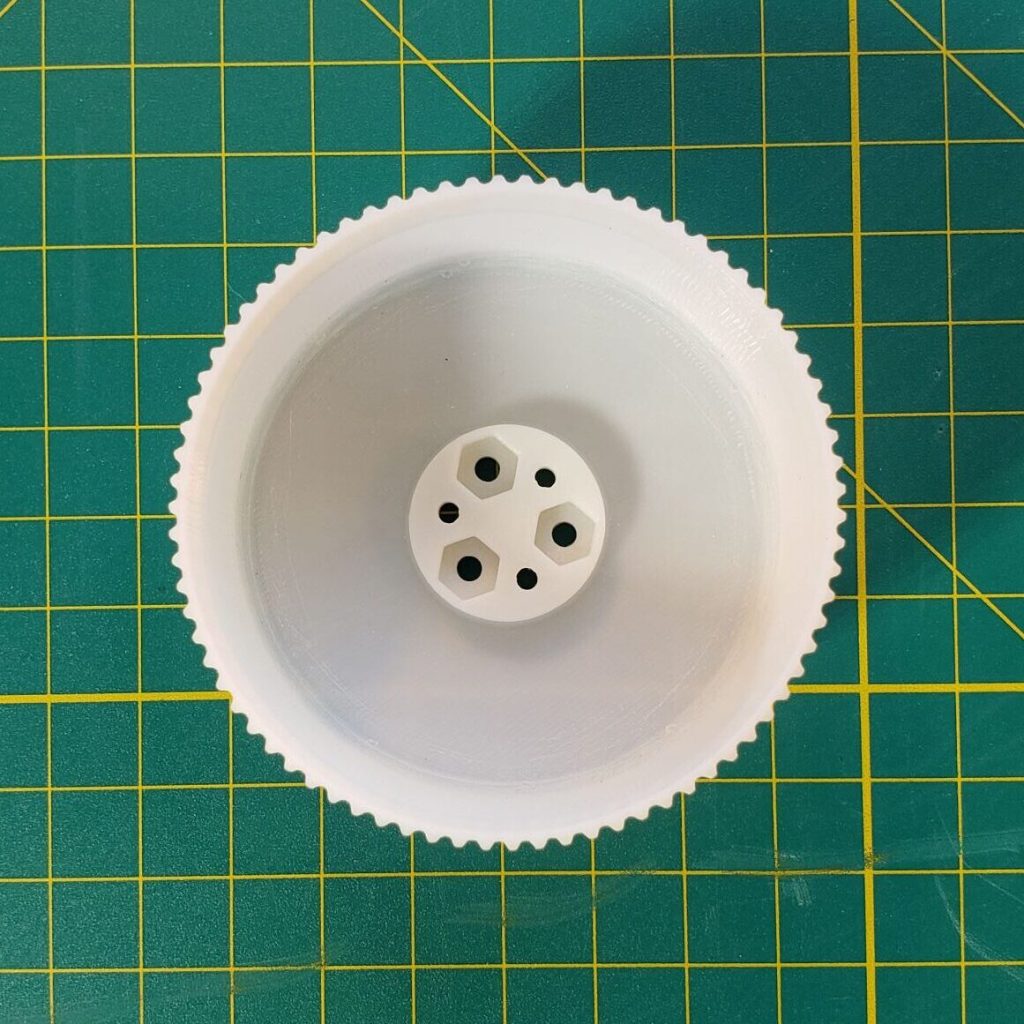
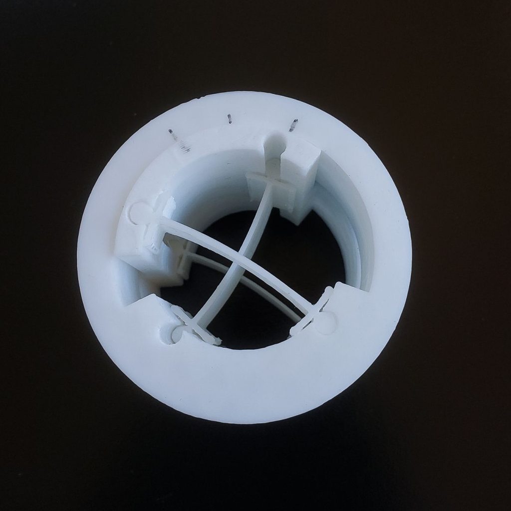
Flex spline “cup”
Flex spline top view
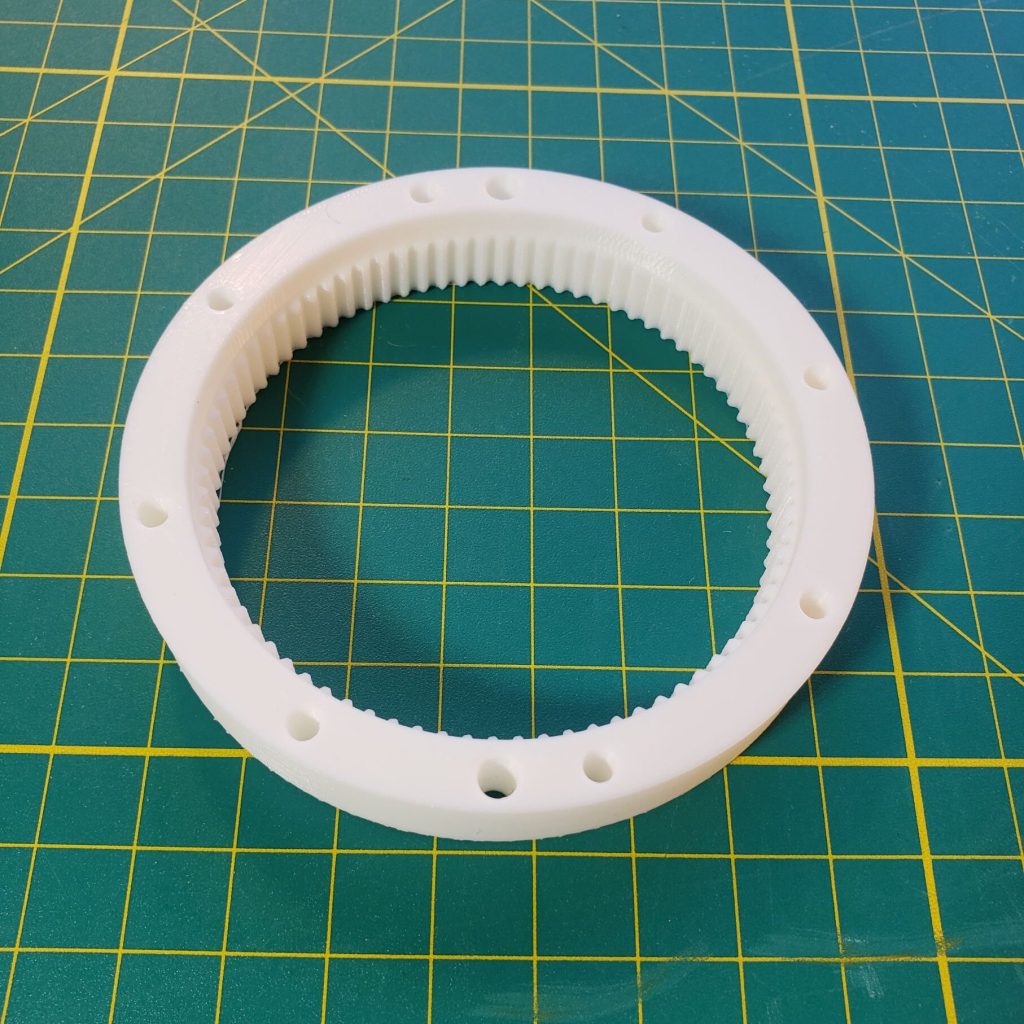
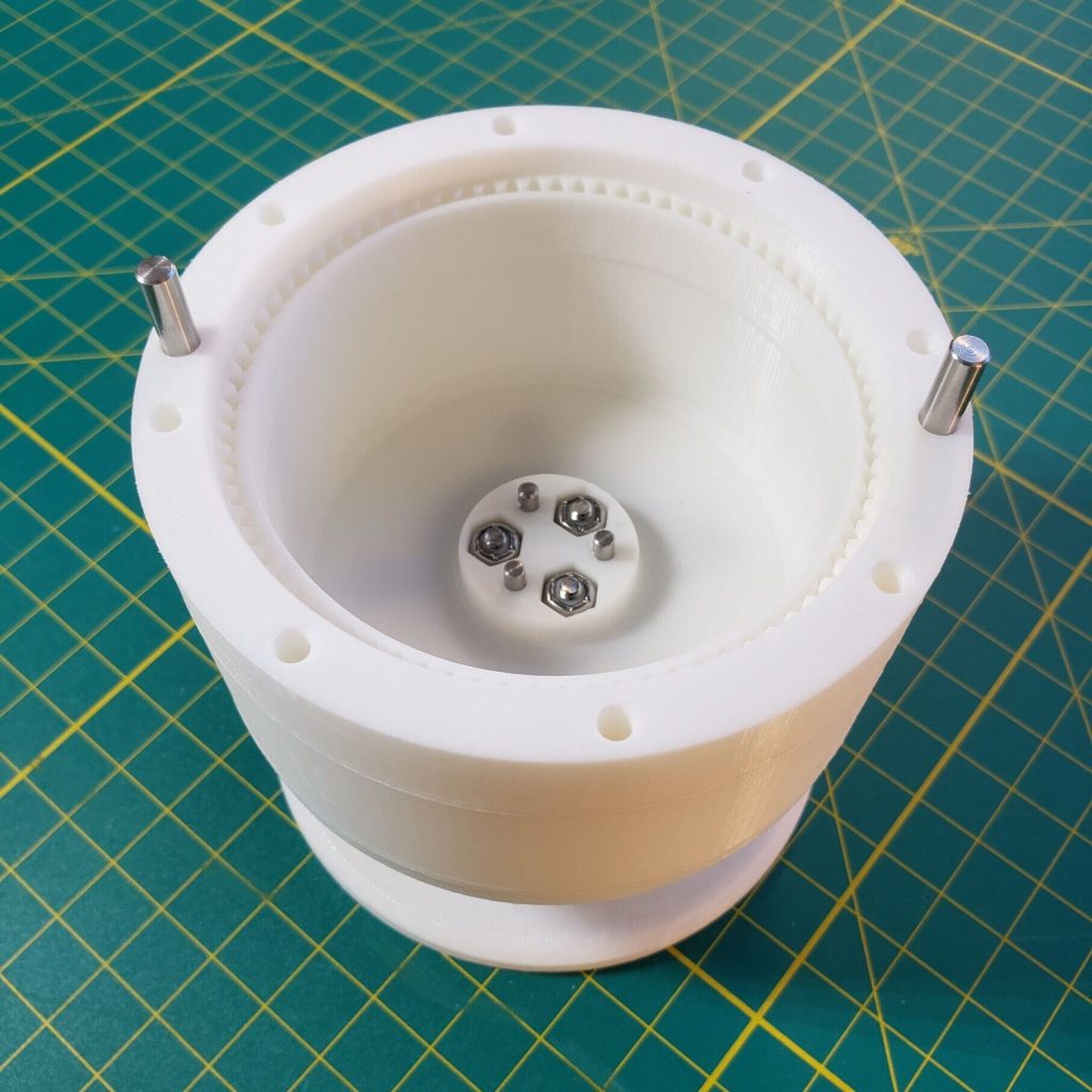
Outer spline. Split from main body so I could test different tooth geometries.
Flex spline mounted to output shaft housing
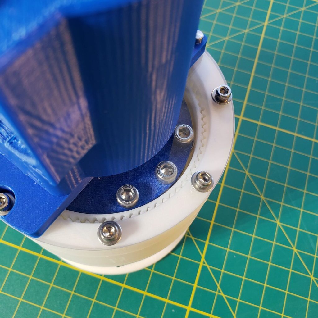
Splines meshing when wave generator inserted

Why I like 3D printing – I’ve seen a lot of 3D print designs that aim to be all ,or mostly, printed which I don’t see the appeal of. If it was cheap and easy enough I’d make this whole thing out of machined metal, but since that’s not cheap or easy, I figure, why not use as many low-cost precision components, like dowels, bearings and hardware as possible? Then I can make the complicated parts out of printed plastic while not sacrificing too much. I’ve been really happy with this approach and am always on the lookout for ways to sneak more performance into my designs, whether it’s with hardware or the designs of the 3D prints themselves. “Tony Stark was able to build this in a cave – with a box of scraps!” is constantly in the back of my mind.
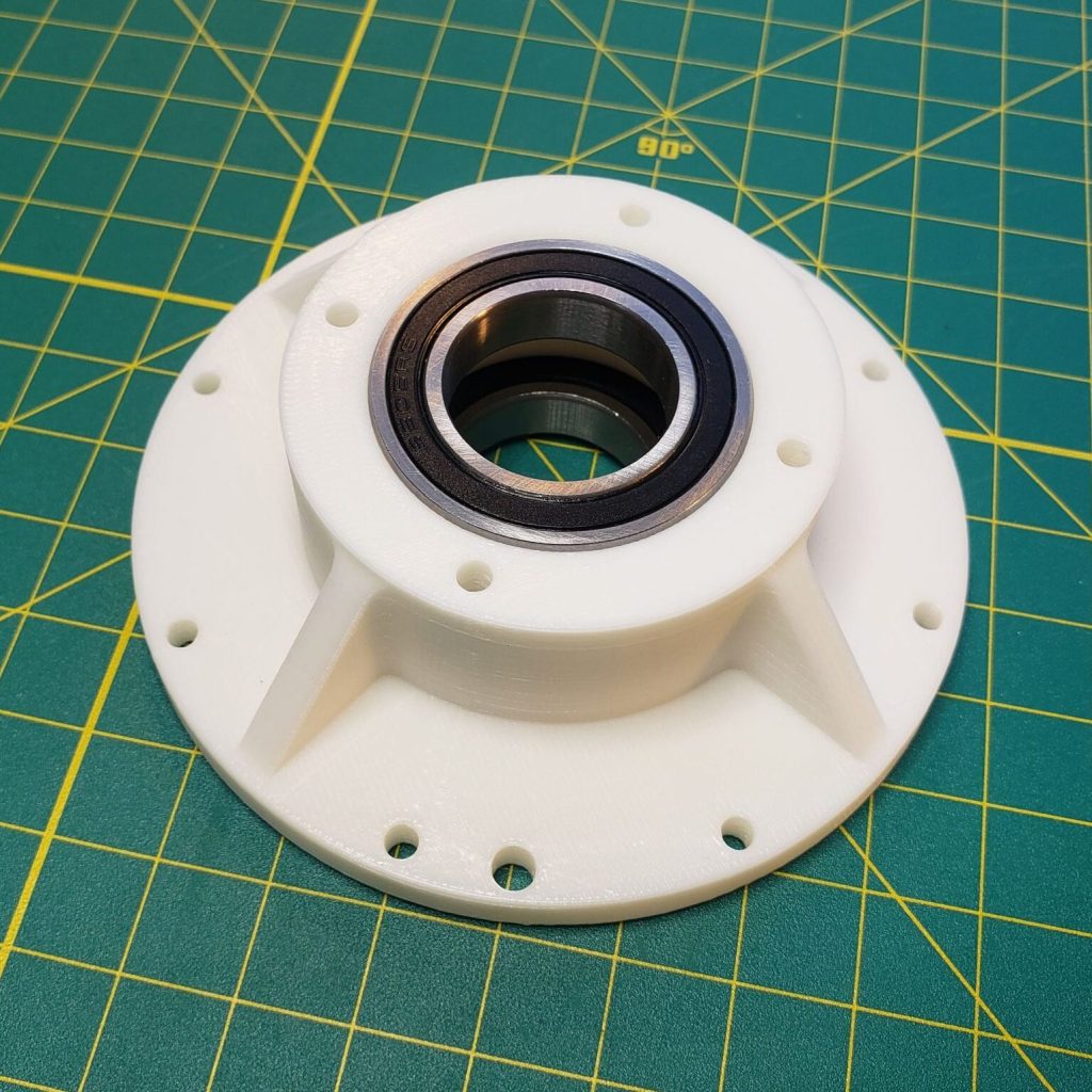
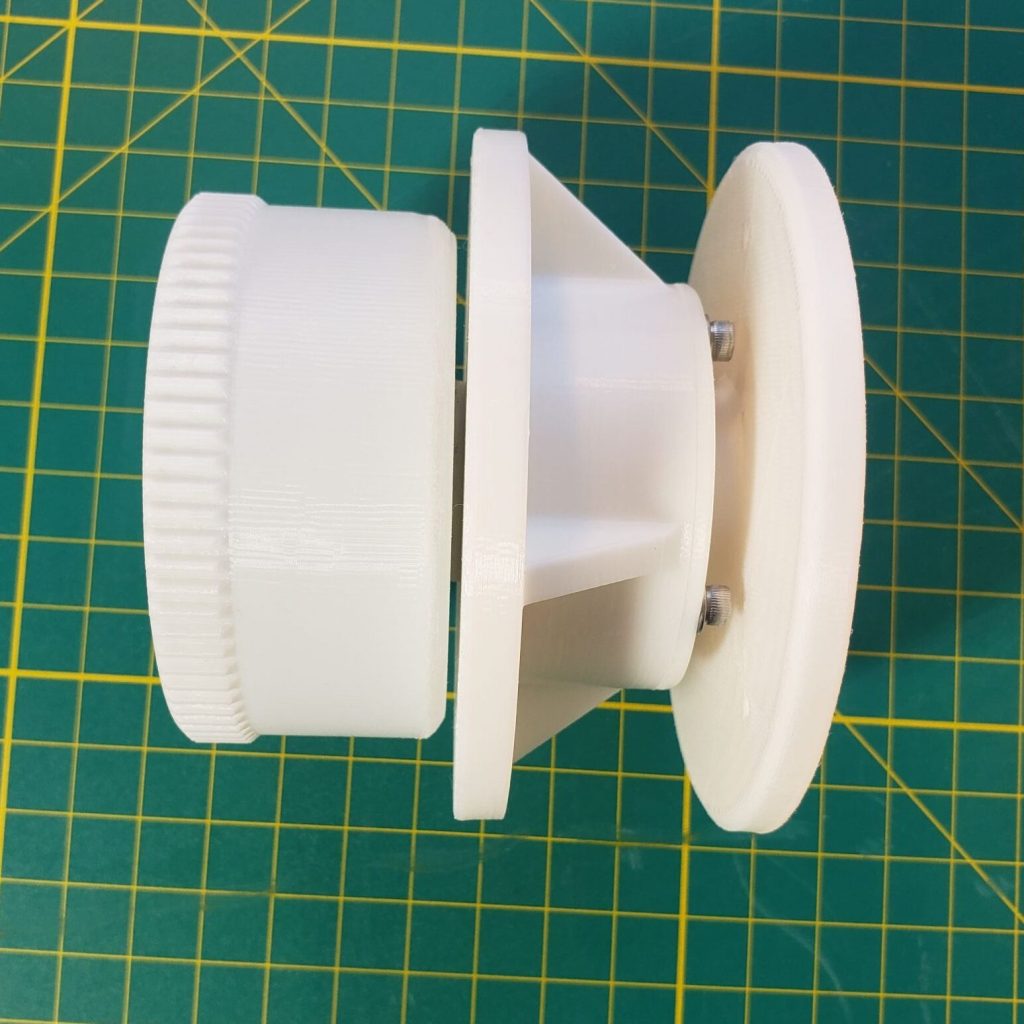
Output shaft housing
Outer spline and flex spline before inserting ellipse

Kinematic coupling – I also attached a kinematic coupling (Wikipedia)(a repeatable and self-aligning fixture) which I had made previously to see what the combined precision of the harmonic drive and kinematic coupling would be. It also provided a standardized interface where I could just print a new ball bearing mount with a different payload/instrument on it and swap them out with no disassembly.
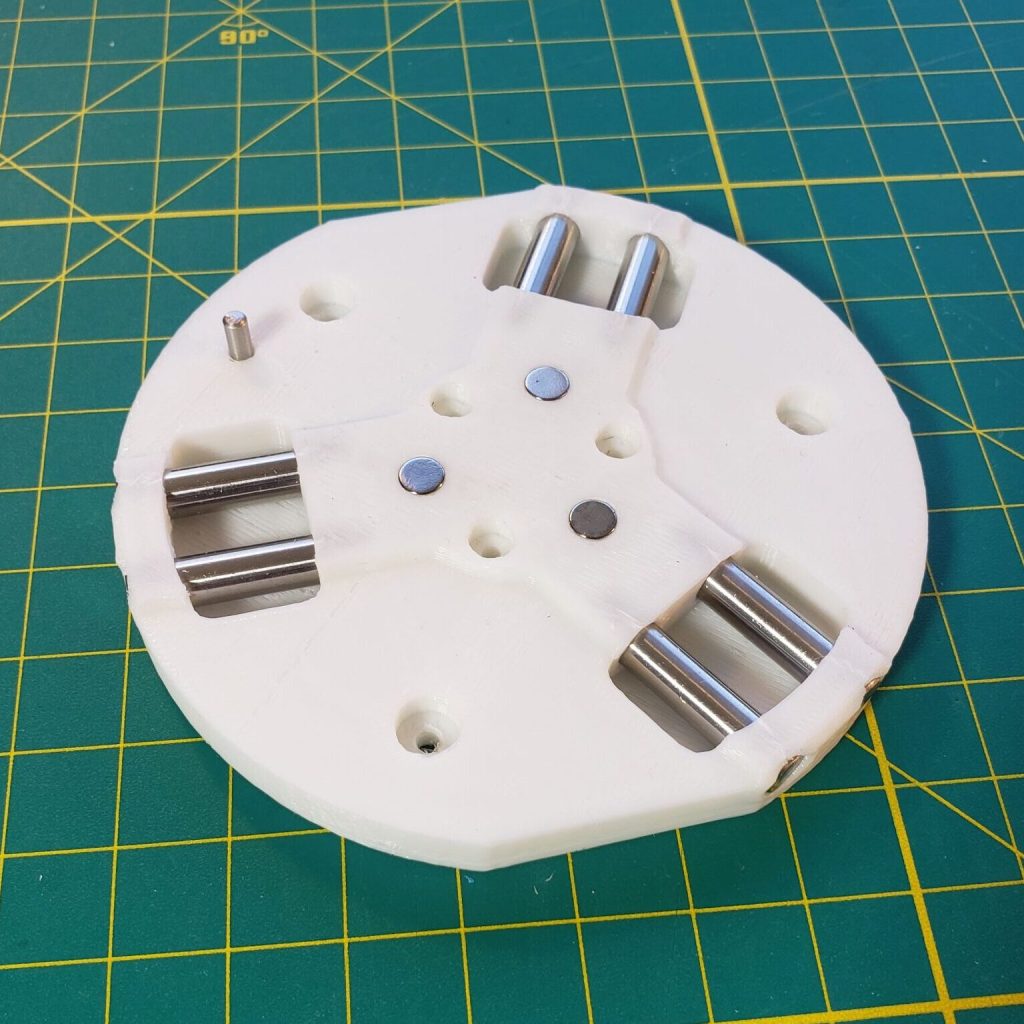
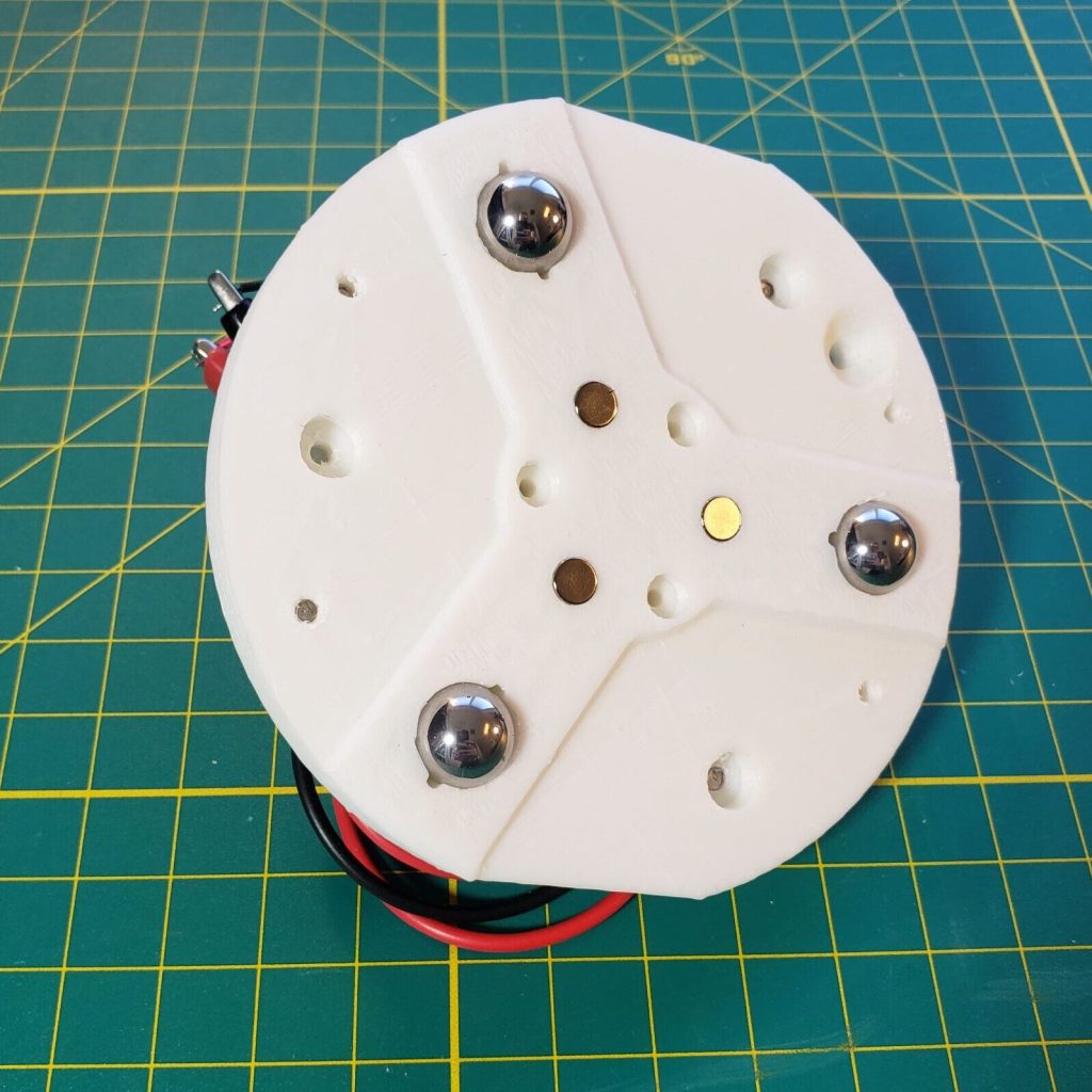
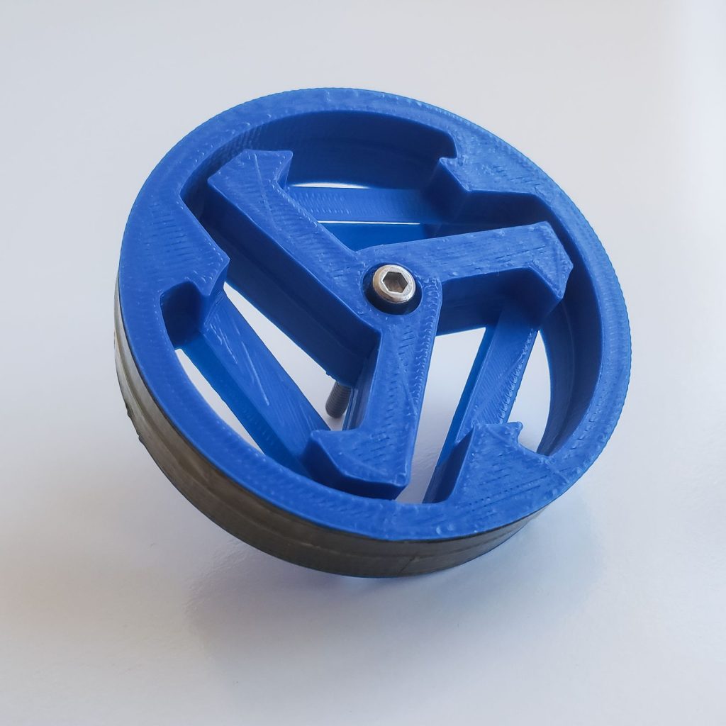
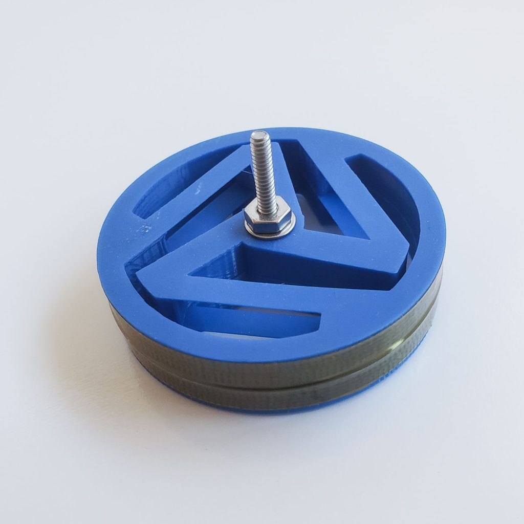
Maxwell (three groove) kinematic coupling base
Maxwell (three groove) kinematic coupling top
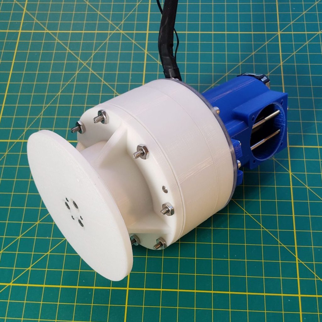
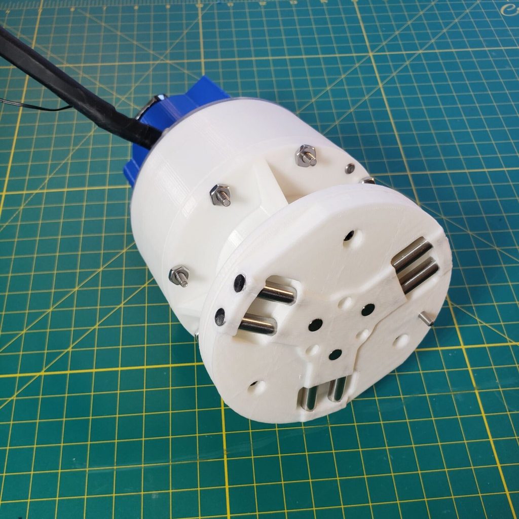
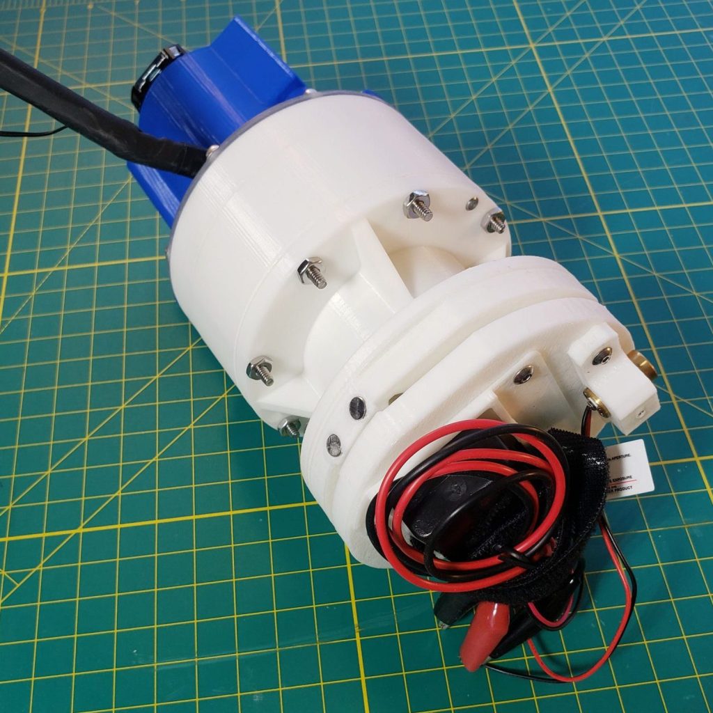
Assembled harmonic drive
Kinematic coupling mounted to harmonic drive

Motor input – The motor is a simple off-the-shelf BLDC (brushless DC) motor driven by an ODrive which is an open source BLDC driver. I want to do more with these ODrives in the future. They’re pretty handy for prototyping although the programming interface is a little cumbersome. With a better UI they could be an industrial “LEGO” type tool.
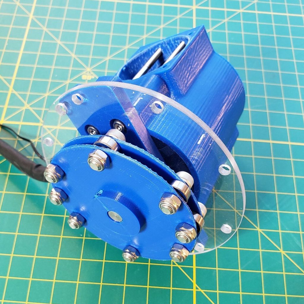
Wave generator ellipse and motor

Specs

  • Tooth count: flex spline (78), outer spline (80)
  • Gear ratio: 78 / (80 – 78) = 39:1
    • flex spline teeth / (outer spline teeth – flex spline teeth)
    • The flex and outer splines typically differ by 2 teeth
  • Repeatability: < .015 deg [0.89 arc-min]
    • Back of envelope:
      • Laser visual position resolution: < 1/32″ = 0.031″
      • Laser distance: 10′-12′
      • No detectable movement of laser position greater than laser visual position resolution
      • Repeatability = arctan(.031″ / 120″) = < .015 deg [0.89 arc-min]

Full assembly and videos
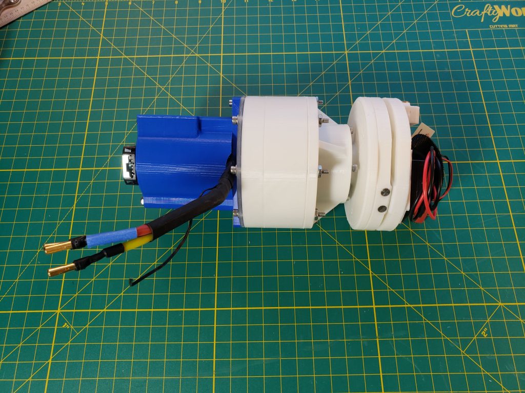
Whole assembly with laser to test performance
Whole assembly from another angle

Monolithic space pointing mechanism

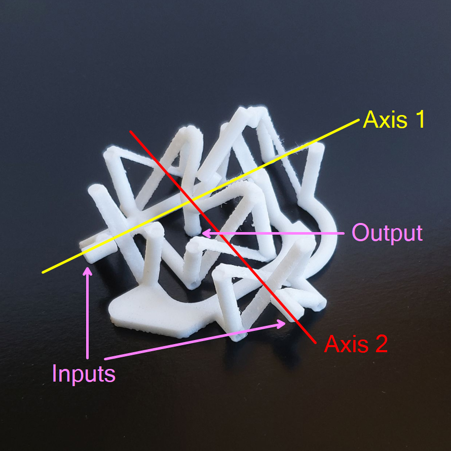
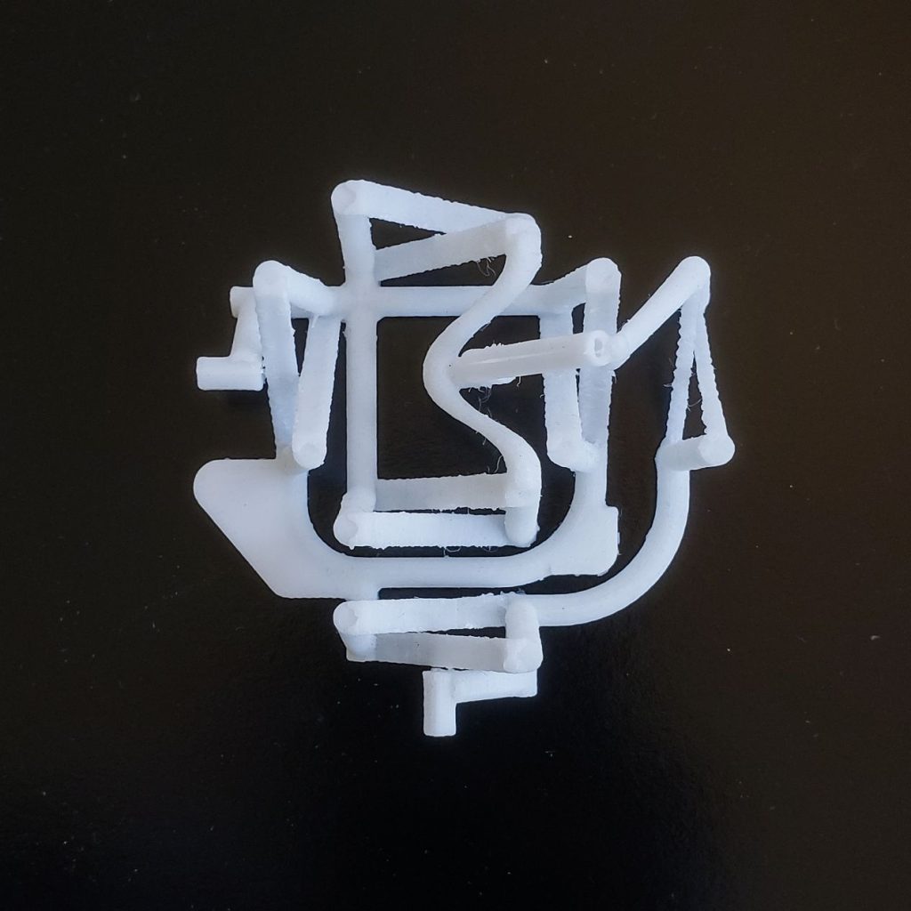
I found a paper called “Monolithic 2 DOF fully compliant space pointing mechanism” while looking for useful flexure combinations and was wondering how a plastic version of the mechanism would behave. The paper describes a mechanism which rotates around 2 independent axes and could be used for an attitude control thruster or for positioning a space antenna (among other applications). It would only have two input actuators and be made out of one 3D printed titanium part.

The paper is by lead author Ezekial Merriam. Additional authors are: J. E. Jones, S. P. Magleby and Larry Howell. A big thanks to Larry (Professor and Associate Academic Vice President of Mechanical Engineering at BYU) who was kind enough dig up the STL file for this and email it to me. The paper has lots of good details about vibration modes (important for space launches), accuracy, repeatability, stiffness and fatigue life.

Each axis has 3 flexure pivots (X’s) which allow for rotation about an axis (yellow and red lines). The inputs are the tubes that are in-line with the two axes. The output is the tube that’s perpendicular to both axes.

If you’re on the lookout for these flexure pivots you’ll see them in lots of space hardware like on the James Webb’s filter wheel (from Launch Pad Astronomy – How James Webb’s Instruments Work – and What They’ll Show Us!)

Coincidentally, a couple months after I contacted Larry about this paper, Derek from Veritasium made a popular video featuring both Larry and this mechanism! Check out “Why Machines That Bend Are Better” below. The STL model has since been made available on Thingiverse, possibly in response to Veritasium’s video (Thingiverse link).


A couple more videos showing the mechanism in action.

Microns from a chopstick

– Taper pin adjuster –

Overview

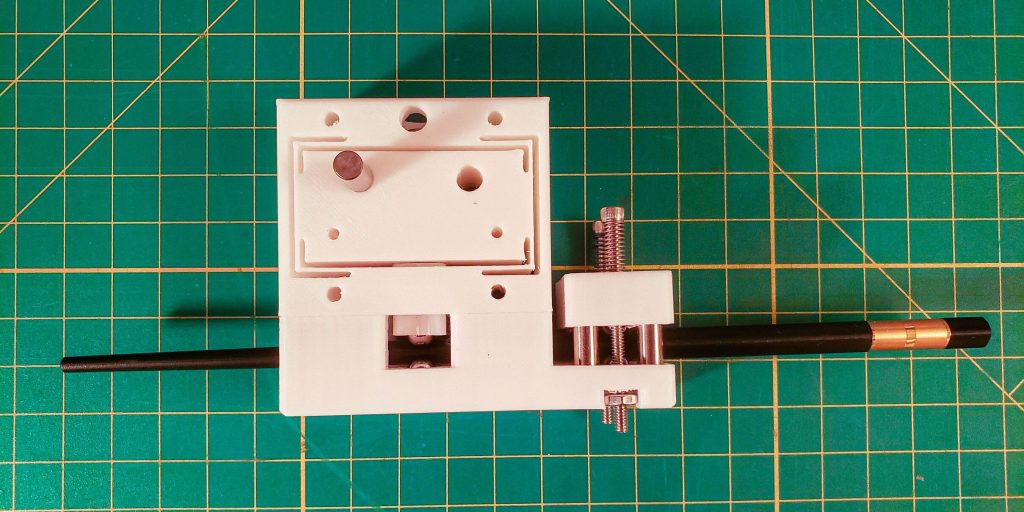
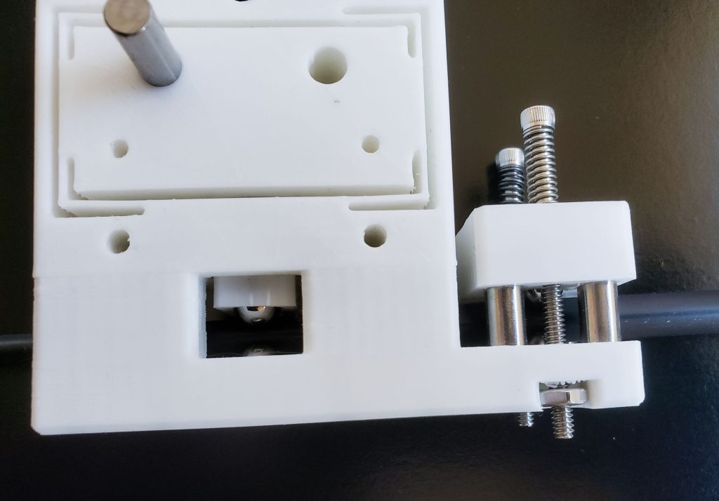
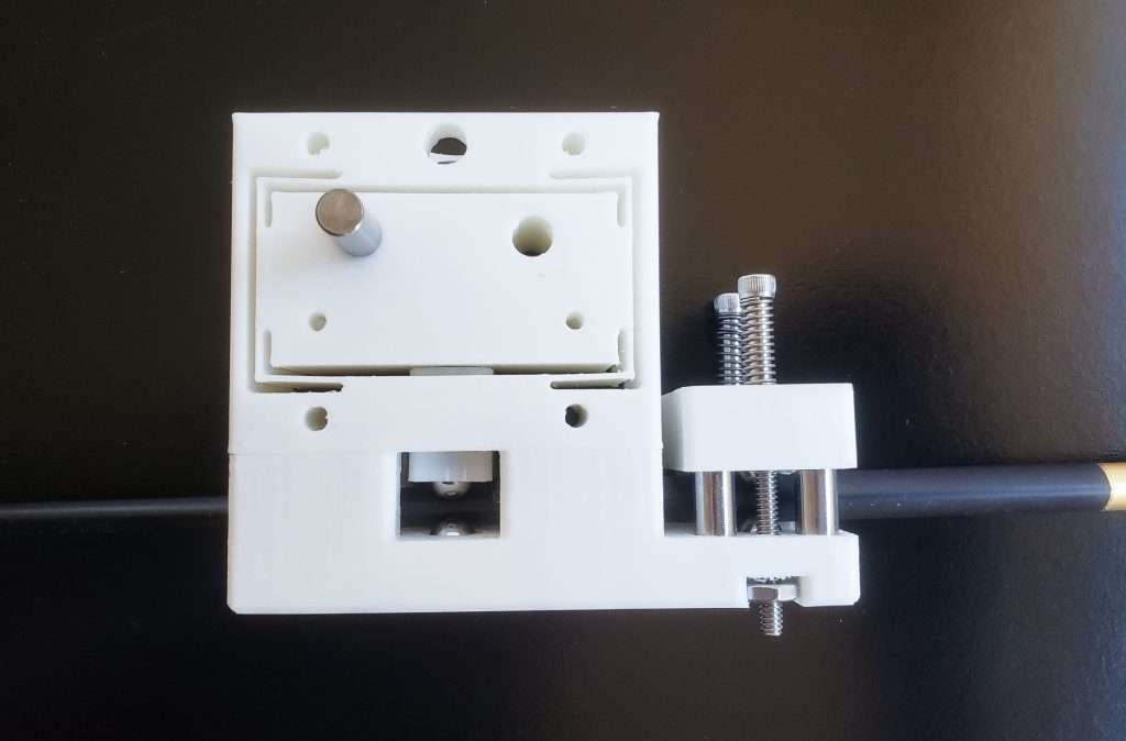
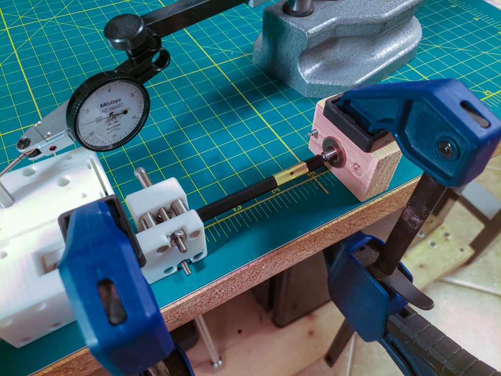
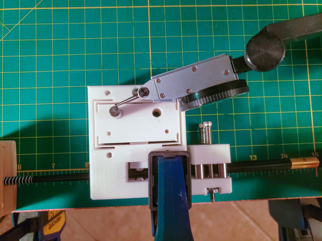
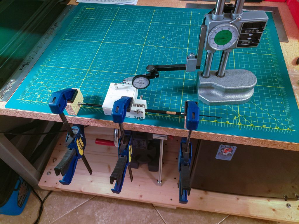
Uses – Fixtures and stages used for manufacturing often require precise alignment to work correctly (punches and dies need to be centered, fiber optics need to be aligned). If you can see or measure the position as you make adjustments, the question becomes ‘how easily can you make adjustments and what mechanism do you use?’. This is a demonstration of the positioning precision you can get from a low-cost taper pin adjustment mechanism (a chopstick and a flexure). It translates left and right motion of the chopstick into vertical motion of a flexure stage using ball bearings in contact with the tapered surface of the chopstick.

Precision adjustment screws – Screws are probably the most useful and ubiquitous adjustment mechanism but they do have downsides. Finer thread pitches require more precise manufacturing which is expensive and the load ratings are generally low. An 80 TPI (thread per inch) adjustment screw is pretty standard for fine adjustments but you only get a resolution of .0125″ per turn and a load rating of about 15 pounds. You can get differential screws and micrometers with resolutions of 0.5 microns [20 millionths of an inch] from Thorlabs but they’re around $120-$400.

Changing form-factor to borrow precision from a CNC machine – A good way to get the benefit of a screw without the form factor and associated manufacturing complications is to unwind the thread into a ramp or wedge which can have a vanishingly small slope, equating to a much higher thread pitch. If you want a ramp that’s axially symmetric you can use a tapered pin. And if you want a cheap tapered pin… you can use a chopstick! Since the plastic ones are injection molded it means you get to borrow the precision of the machine that made the chopstick mold for basically free. Even better, if you combine a chopstick taper pin with a standard 80 TPI adjustment screw, you can compound the adjustment screw resolution to get an effective TPI of 5,882!

Limitations – You can’t rely on this mechanism to be accurate or repeatable (in the technical sense of those words). For example, the surface will deform slightly where it contacts the retention balls and the taper isn’t linear (but it is gradual, which is great). But, if all you’re looking for is high precision positioning then this is all you need since you can use an indicator on the output to close the feedback/adjustment loop.

Construction

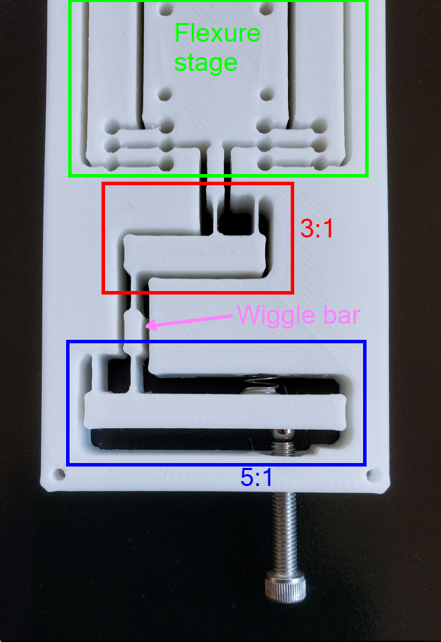
Flexure stage – The flexure stage is just to keep the motion linear and remove backlash. In practice you could waterjet this part out of metal and use a leaf spring clamp to hold the moveable block in place once the chopstick is removed.

Movement reduction – To move the chopstick back and forth, you need some kind of adjustment method. I used a relatively common Thorlabs 80 TPI screw for this ($10). The chopstick has a taper of about 0.78 deg., or 0.0136″ change in diameter per 1″ of travel. The adjustment screw advances 1″ per 80 revolutions meaning you get a diameter increase of 0.0136″/80 = 0.00017″ per screw revolution (an effective TPI of 5,882). Assuming you can accurately move the screw in 10 increments per revolution, you get an output resolution of 1.7×10^-5 inches, about 0.43 microns, on par with expensive micrometers and differential screws!

Performance

So how does it work in practice? I found it to be remarkably smooth and reliable in practice and could easily stop at half micron increments on a 1 micron dial indicator (not shown in videos). I could also go back and forth smoothly, meaning the spring preload was effective. You could obviously just buy a micrometer for the same purpose, this was more of a demonstration of how simply precision movement can be achieved.

Measuring full precision of adjustment setup

Gelbart 15 to 1 flexure

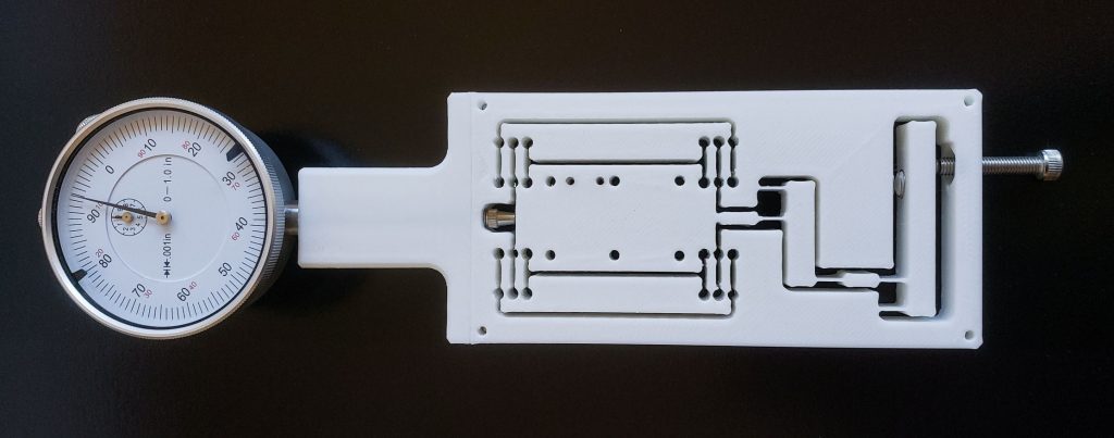
I don’t know if this flexure has an official name but I’m naming this build after Dan Gelbart since I first saw it in his flexure video (below) and he’s a personal hero of mine. His YouTube series on building prototypes is a must-watch for anybody interested in making functional, precise equipment cheaply and quickly.

What’s cool about this mechanism?

Typical of flexures, this mechanism is smooth, has no backlash or stiction and is very repeatable over small distances (I haven’t fully characterized its performance so not sure about larger distances). You can hit fractions of a thou all day with a plastic 3D printed version and Dan Gelbart manages to get 10 nm [0.4 millionths of an inch] with his aluminum waterjet version. When clamped properly you can reliably get 0.5 micron or 20 millionths of an inch on the 3D printed version!

The thing that’s appealing to me about these kinds of demonstrations is that the geometry is doing all the work. It’s all about design, not what kind of manufacturing tolerances you can achieve. This was 3D printed on a standard printer, using cheap stepper motors and a couple bucks of filament and maybe $1 of hardware. Of course there are limitations like thermal stability, travel distance and accuracy etc., but if your question is something like “what kind of precision can be achieved using the least expensive components”, this is a good candidate.

Cost vs. precision curve – For example, if you want to minimize Precision*Cost what are your options compared to this device? Ignoring the dial indicator and assuming the print costs $10 of filament + printer wear, the equation above is 2×10^-5 inch precision * $10 cost = 2×10^-4 ($*in). Keeping this value constant, could you achieve 10 times more precision (50 nm) for 10 times more ($100)? Possibly, but you’d have to be pretty selective about components and design. How about 10 times less precision (.0002″) for 10 times more cost ($1)? Again, maybe, but it would be tricky. This indicates that this mechanism is within an order of magnitude for the level of precision that can be achieved in this price range.

Mechanism details

The bottom of the fixture has a 5 to 1 lever that the screw pushes against with a spring counteracting it for preload. A wiggle bar transmits motion to the next stage which is a 3 to 1 lever. This multiplies together with the first lever to give a 15 to 1 reduction in travel. I found it very helpful to have the adjustment screw contacting a ball bearing to maintain a single point of contact as the lever rotates and to compensate for the inaccurate screw tip. This point contact is common in micrometers and other fine adjustment systems.

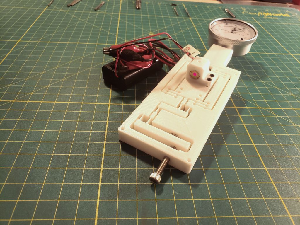
The next section is a standard linear flexure mechanism. Dan Gelbart’s stage has about 2mm travel with 1 micron deviation from perfect linearity. I would like to measure the specs of mine but need to create a fixture that can measure the linearity accurately enough. It’s 3d printed and probably has terrible thermal stability but I did take the time to drill out the holes on the living hinge sections of the linear stage which makes it a little more accurate.

The laser beam is to measure linearity of the flexure stage travel (no noticeable wiggle in the beam from 10′ away during adjustment).

Mechanism precision

I’m sure I could use a micrometer for adjustment but I was already maxing out the resolution of the dial indicator (.0005″) with a 10-32 adjustment screw. With the 15 to 1 reduction, the effective thread pitch is 15 * 32 = 480 TPI (teeth per inch), just over .002″ per turn. A quarter turn is the maximum resolution of my indicator (.0005″). I also measured with a 1 micron indicator and was able to achieve 0.5 micron movements! You have to be very careful about bumping the system at that scale though, since any wobble in the screw can result in jumpy readings.

If I used an 80 TPI adjustment screw I could get .0002″ [5 micron] with 1/4 screw turn. With a micrometer (which uses another cool mechanism, a differential screw), I could get graduations of .001″, resulting in a theoretical resolution of 152 nm. I’m sure at those scales the accuracy and repeatability would be very inconsistent though. I’ve been looking into building an interferometer to see how low I could really go.

Differential screw

This was an attempt to make a differential screw. I got interested in them after watching this video from Tom Lipton of Ox Tools/Berkeley Lab. Tom’s channel is amazing and has lots of ideas for precise, useful and clever projects.

How differential screws work

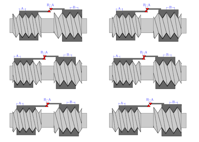
Main principal – Differential screws allow you to make really precise adjustments using two screws with slightly different thread pitches – one screwed into a fixed part and one screwed into a moving part. The moving part will move a tiny bit relative to the fixed part due to the differences in the pitch. Another way to think of it is that the coarse pitched screw advances by a certain amount and the fine pitched screw backs off by almost the same amount, resulting in a large reduction from the input movement to the output movement. Screws are already good for adjustment since they convert large rotational movement into small linear movement, so stacking this effect with the differential screw effect results in surprisingly good precision. Regular adjustment screws only go up to about 100-120 threads per inch so this is one of the only ways to get more precision while still using some type of screw mechanism.

Wikipedia – Differential screw

The effective TPI is calculated as:

    \[ \frac{1}{TPI_{eff}} = \frac{1}{TPI_1} - \frac{1}{TPI_2} = P_{eff} \]

Combinations – Some common combinations are:

  • 10-24 with 10-32 (96 TPI)
  • 1/4″-20 with 1/4″-28 (70 TPI)
  • 1/4″-28 with 10-32 (224 TPI)
  • M4 x 0.7 with M5 x 0.8 (254 TPI)

If you combine metric and imperial threads you can get some crazy combinations like 4064 TPI for a 10-32 and M5x0.8 screw – just a quarter thou per revolution!

Build and results

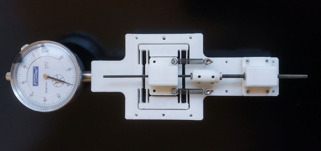
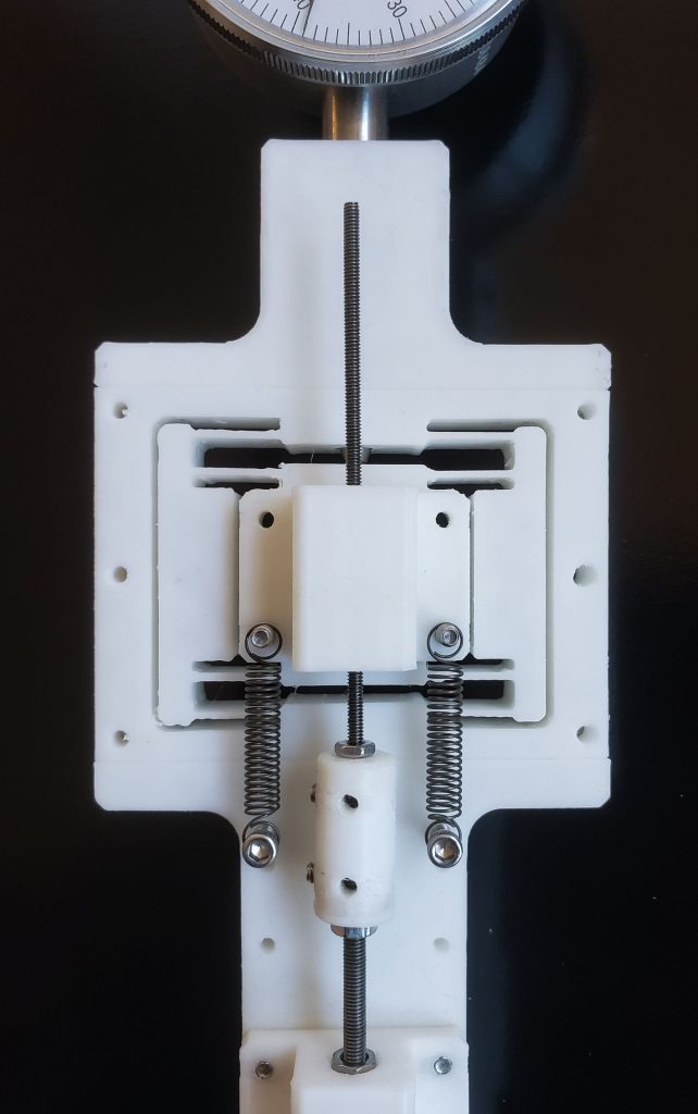
I printed swappable blocks to test different thread combinations and joined long sections of threaded rod together with a printed shaft coupler. The flexure is just to get stiction-free linear motion from a 3D print which allows for more accurate readings. Unfortunately, my setup was kind of a disaster.

Asymmetrical loading – With designs like this you want all your loads to be symmetric so nothing is twisting or bending. I decided to chance it with this design and put everything above the plane of the flexure but this caused deformation in the print and resulted in jerky motion.

Bad threads and thread engagement – Even with preload springs, the motion was very uneven. In Tom Lipton’s video he uses a brass screw for smoother motion and has far more threads engaged. My setup just had nuts set into plastic. There was a lot of clearance between the rod threads and the nut threads and the nuts rocked in their plastic sockets. The stick/slip action in the nuts also made the readings jump around a lot. The shaft coupler also wasn’t tight enough which meant the the whole thing wobbled and tended to buckle since the threaded rods were so long.

Stiffness – Some parts were too stiff and some parts were too flexible so it was easy to bend things in a way that changed the reading significantly. I didn’t have the equipment for it but I think a screw with both external and internal threads like in Tom’s video or the inside of a micrometer would be better – much more rigid and everything would move at the same time so there wouldn’t be uneven motion.

Some standard flexure components

This first one is a flexure pivot, a type of flexure bearing (Wikipedia) that rotates smoothly about the cylinder axis with no friction. Because of parasitic errors the rotating part eventually makes contact with the stationary wall so this design has limited range of motion but it also has close to zero wear since no parts are sliding or rolling on other parts.

This next one is a diaphragm flexure. It uses three sets of parallel beam flexures to keep the mechanism stiff in all directions besides the one it’s moving in. However it does introduce some twist into the moving part (kind of a screw motion). They’re used in voice coils and other systems where you want no friction/stiction, long life and well defined movement. I had seen similar designs in fluid check valves and wondered how hard it would be to make one.